ProSoft Technology MVI46-MCM User Manual
Page 15
MVI46-MCM ♦ SLC Platform
Start Here
Modbus Communication Module
User Manual
ProSoft Technology, Inc.
Page 15 of 108
March 29, 2011
1.4
Installing the Module in the Rack
If you have not already installed and configured your SLC processor and power
supply, please do so before installing the MVI46-MCM module. Refer to your
Rockwell Automation product documentation for installation instructions.
Warning: You must follow all safety instructions when installing this or any other electronic
devices. Failure to follow safety procedures could result in damage to hardware or data, or even
serious injury or death to personnel. Refer to the documentation for each device you plan to
connect to verify that suitable safety procedures are in place before installing or servicing the
device.
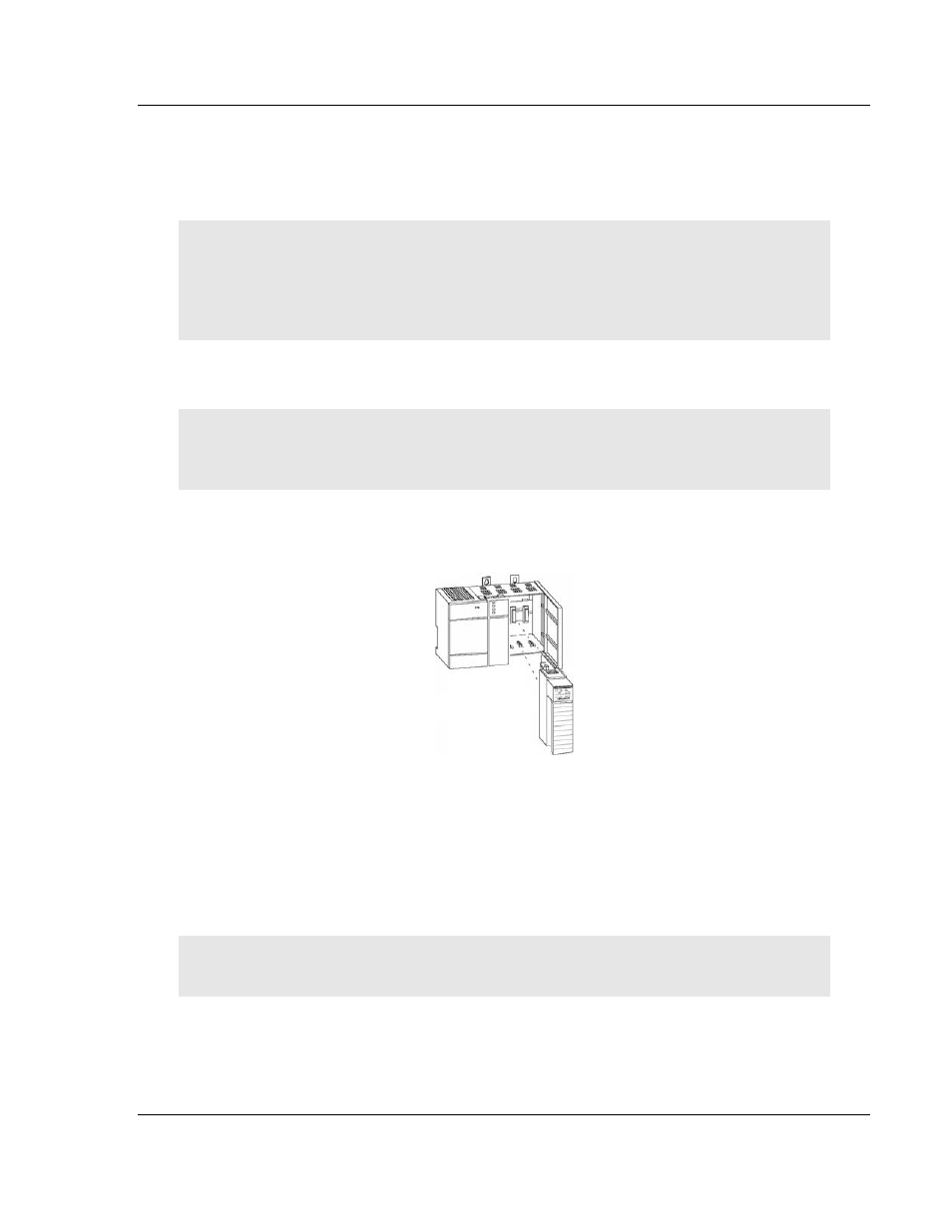
After you have checked the placement of the jumpers, insert MVI46-MCM into
the SLC™ chassis. Use the same technique recommended by Rockwell
Automation to remove and install SLC™ modules.
Warning: This module is not hot-swappable! Always remove power from the rack before
inserting or removing this module, or damage may result to the module, the processor, or other
connected devices.
1 Turn power OFF.
2 Align the module with the top and bottom guides, and slide it into the rack
until the module is firmly against the backplane connector.
3 With a firm but steady push, snap the module into place.
4 Check that the holding clips on the top and bottom of the module are securely
in the locking holes of the rack.
5 Make a note of the slot location. You will need to identify the slot in which the
module is installed in order for the sample program to work correctly. Slot
numbers are identified on the green circuit board (backplane) of the SLC
rack.
6 Turn power ON.
Note: If you insert the module improperly, the system may stop working, or may behave
unpredictably.