ProSoft Technology MVI46-MCM User Manual
Page 63
MVI46-MCM ♦ SLC Platform
Reference
Modbus Communication Module
User Manual
ProSoft Technology, Inc.
Page 63 of 108
March 29, 2011
All data transferred between the module and the processor over the backplane is
through the M0 and M1 files. Ladder logic must be written in the SLC processor
to interface the M-file data with data defined in the user-defined data files in the
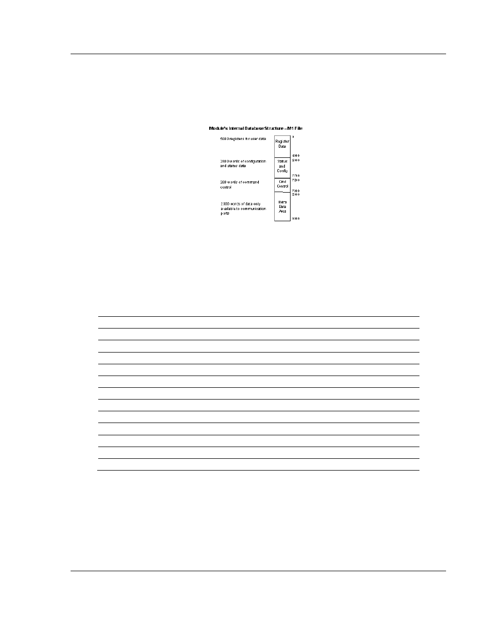
SLC. All data used by the module is stored in its internal database. The following
illustration shows the layout of the database:
User data contained in this database is continuously read from the M1 file. The
configuration data is only updated in the M1 file after each configuration request
by the module to the SLC. All data in the M1 file is available to devices on the
Modbus Master/Slave networks. This permits data to be transferred from these
devices to the SLC using the user data area. Additionally, remote devices can
alter the module's configuration, read the status data, and issue control
commands. Block identification codes define specific functions to the module.
The module uses the following block numbers:
M0 Offset
Description
Length
0 9001
1
1 to 6
Backplane Setup
6
11 to 40
Port 1 Configuration
30
41 to 70
Port 2 Configuration
30
71 to 80
Port 1 Command # 0 Definition
10
81 to 90
Port 1 Command # 1 Definition
10
91 to 1060
Port 1 Command # 2 to # 98
980
1061 to 1070
Port 1 Command # 99 Definition
10
1071 to 1080
Port 2 Command # 0 Definition
10
1081 to 1090
Port 2 Command # 1 Definition
10
1091 to 2060
Port 2 Command # 2 to # 98
980
2061 to 2070
Port 2 Command # 99 Definition
10
Each block has a defined structure depending on the data content and the
function of the data transfer as defined in the following topics.