Hmc controller ip core – Altera Hybrid Memory Cube Controller User Manual
Page 22
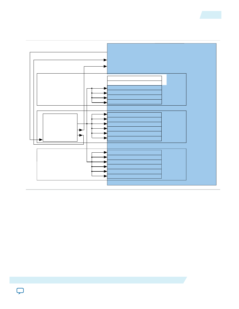
Figure 2-7: Transceiver PLL Connections Example with xN Bonding Scheme
Example connections between a full-width HMC Controller IP core and a single ATX PLL IP core in xN
bonding mode.
ATX PLL
pll_powerdown
pll_locked
pll_cal_busy
HMC Controller IP Core
Txvr Block N
Txvr Block N+1
Txvr Block N+2
pll_locked
pll_cal_busy
pll_powerdown
tx_bonding_clocks (Channel 5)
tx_bonding_clocks (Channel 4)
tx_bonding_clocks (Channel 3) (Lane 15)
tx_bonding_clocks (Channel 2) (Lane 14)
tx_bonding_clocks (Channel 1) (Lane 13)
tx_bonding_clocks (Channel 0) (Lane 12)
tx_bonding_clocks (Channel 5) (Lane 11)
tx_bonding_clocks (Channel 4) (Lane 10)
tx_bonding_clocks (Channel 3) (Lane 9)
tx_bonding_clocks (Channel 2) (Lane 8)
tx_bonding_clocks (Channel 1) (Lane 7)
tx_bonding_clocks (Channel 0) (Lane 6)
tx_bonding_clocks (Channel 5) (Lane 5)
tx_bonding_clocks (Channel 4) (Lane 4)
tx_bonding_clocks (Channel 3) (Lane 3)
tx_bonding_clocks (Channel 2) (Lane 2)
tx_bonding_clocks (Channel 1) (Lane 1)
tx_bonding_clocks (Channel 0) (Lane 0)
tx_bonding_clocks[5:0]
UG-01152
2015.05.04
Adding the External PLL
2-13
Getting Started with the HMC Controller IP Core
Altera Corporation