2 control panel, 3 solvent curve fdl 115 – BINDER FDL 115 User Manual
Page 21
FDL (E2.1) 02/2015
page 21/75
2.2 Control panel
(6) (5) (4) (3)
(2) (2a) (2b) (1)
Figure 4: Control panel of FDL 115 standard unit
(1) Main power switch ON/OFF
(2) Temperature safety device class 2
(2a) Red pilot lamp for temperature safety device class 2
(2b) RESET key for temperature safety device
(3) Red indicator light “AIR”: Heating turned off during prepurge or due to insufficient exhaust air
stream (loss of technical ventilation)
(4) Pushbutton “START”: starts the fan and the prepurge procedure
(5) Temperature program controller RD3
(6) Solvent curve: Highest permissible amount of solvent G
total
[g] as a function of the drying tempera-
ture
2.3 Solvent curve FDL 115
0,00
5,00
10,00
15,00
20,00
25,00
30,00
35,00
50 60 70 80 90 100 110 120 130 140 150 160 170 180 190 200 210 220 230 240 250 260 270 280 290 300
Temperature [°C]
G
to
ta
l [g
]
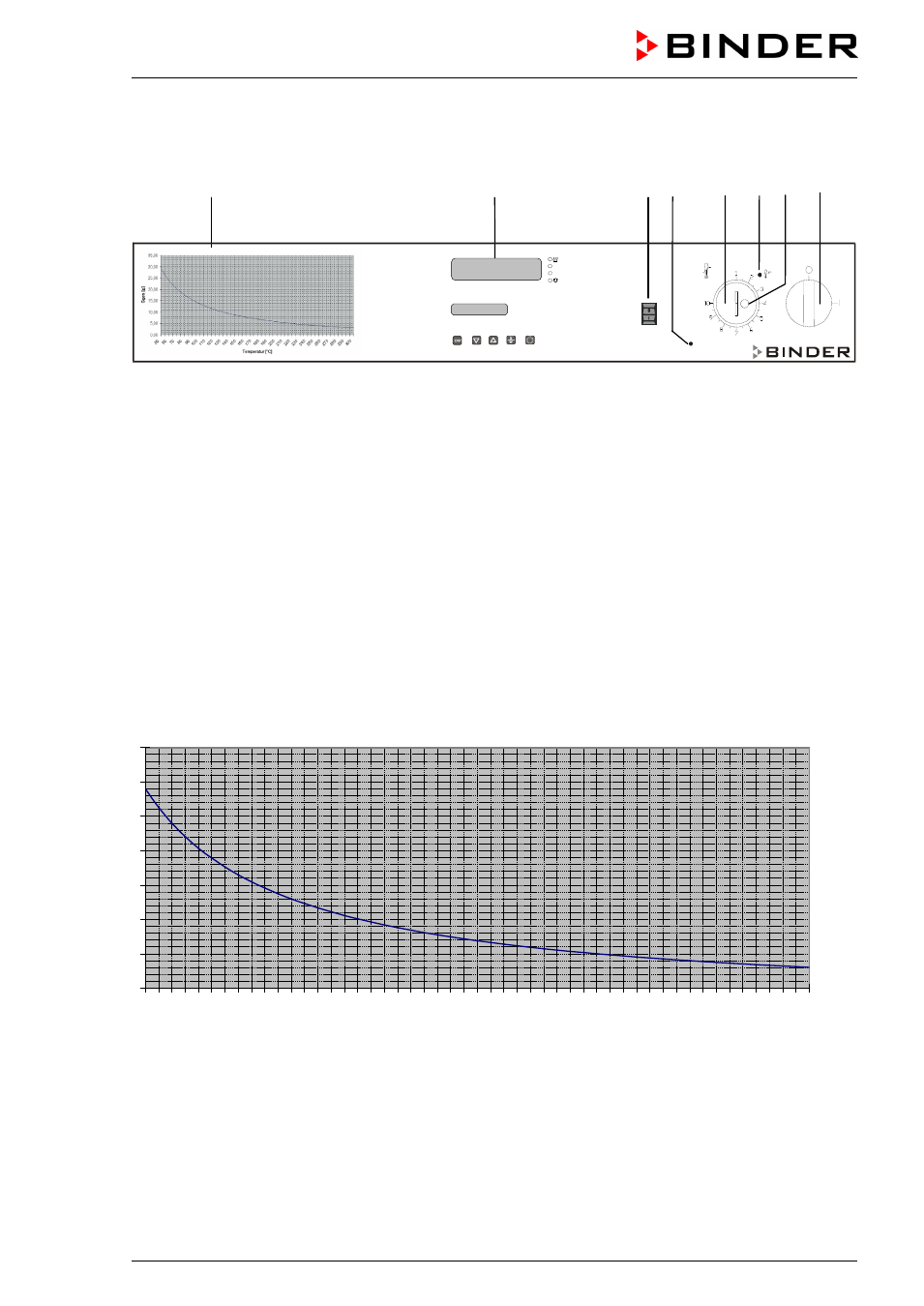
Figure 5: Solvent curve FDL 115
The diagram shows the highest permissible solvent quantity G
total
[g] in the steam room in correspond-
ence to the drying temperature. This is based on the calculation acc. to EN 1539:2009 considering the
unit specific data, an assumed molecular weight of the solvent of 100g/Mol, and a lower explosion limit of
40g/m
3
at 20 °C / 68 °F and at 760 Torr (1013 hPa) (assumptions for unknown solvents acc. to EN
1539:2009).
AIR
START