BINDER FDL 115 User Manual
Page 27
FDL (E2.1) 02/2015
page 27/75
In
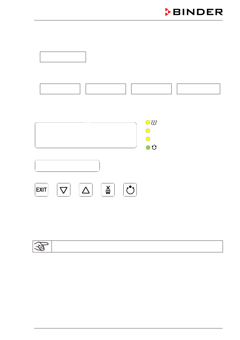
Display 1 of the controller the actual temperature Value is shown.
•
With inactive week program timer:
In
Display 2 of the controller the actual date and time are displayed. Example:
15.01.07 13:52
•
With active week program timer:
In
Display 2 of the controller the actual date and time and the states of the week program timer chan-
nels are displayed. Examples:
15.01.07 13:52 - -
15.01.07 13:52 - �
15.01.07 13:52 � -
15.01.07 13:52 � �
Channel 1 Off,
Channel 2: Off
Channel 1: Off,
Channel 2: On
Channel 1: On,
Channel 2: Off
Channel 1 On,
Channel 2: On
(3a) LED Heating active
(3b) (no function)
(3c) (no function)
(3d)
LED lit: program operation
LED flashing: exceeding of the
tolerance limits in “Fixed value
entry mode” or in “Program op-
eration”. In program operation:
program interruption.
Figure 6: RD3 program controller
The program controller RD3 permits programming of temperature cycles.
Two programs with up to 10 sections each or one program with up to 20 sections can be entered (setting
in the user level, chap. 10).
When changing from 2 programs to 1 program or vice-versa, existing programs are deleted
The maximum length of an individual program section can be set to either 99 hs 59 min or to 999 hs 59
min (setting in the user level, chap. 10). This setting is then valid for all program sections.
Programming can be done directly via the controller keyboard or graphically at the computer using the
software APT-COM™ 3 DataControlSystem (option, chap. 13.1) specially developed by BINDER.
Display 1
Display 2