2 getting started, Office setups, Unpacking and connecting – Audioscan Verifit 2 User Manual
Page 20
Verifit
®
User's Guide Version 4.2 © June 2015
2 Getting Started
This section provides instructions for unpacking the Verifit and connecting various components and associated
items.
Office setups
1. Conventional. In the standard setup the Verifit display unit and test box are placed either side by side or co-
linear (test box in front) on the same surface. The distance between them is only limited by the test box cable
that connects them. If an external speaker is not being used, the display unit should be positioned so that a client
will be less than 100cm (3 ft.) from the speakers above the display (see also, Positioning the client).
2. Wall mounted. The display unit can be mounted on a wall bracket with a standard VESA mount. Use care to
route cables appropriately to avoid accidental damage and avoid mounting the Verifit where it will protrude into
walkways or other thoroughfares. Screws supplied with the Verifit should be kept installed when not using a
wall mount. For wall mounting longer screws will be necessary. Length will depend on thickness of mount.
IMPORTANT: Please ensure that any screws used do not exceed a length which would cause them to penetrate
the Verifit rear panel to a depth greater than 16mm (5/8").
3. Remote operation. As the Verifit can be run from your PC desktop in On-top mode, more unconventional
office setups are possible as the display unit does not necessarily need to be in front of the practicioner (see also,
Networking).
Unpacking and connecting
1. Carefully unpack the two parts of the Verifit and check the contents of the shipping box against the enclosed
packing list. Note that some parts may be packed inside the test chamber.
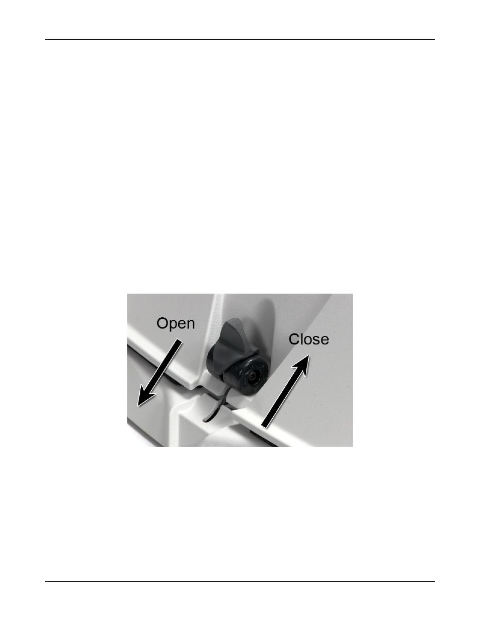
2. Locate the included wireless mouse and turn it on using the switch on the underside. The wireless receiver is
already connected to the Verifit.
3. Connect the test box via the test chamber cable to the rear of the main display unit. The cable can be routed
under the display unit to the test chamber if the test chamber will be used in front to the display unit. Note:
all on-ear functions will operate without the test box connected to the display unit.
20