Microphone connection – Audioscan Verifit 2 User Manual
Page 21
Verifit
®
User's Guide Version 4.2 © June 2015
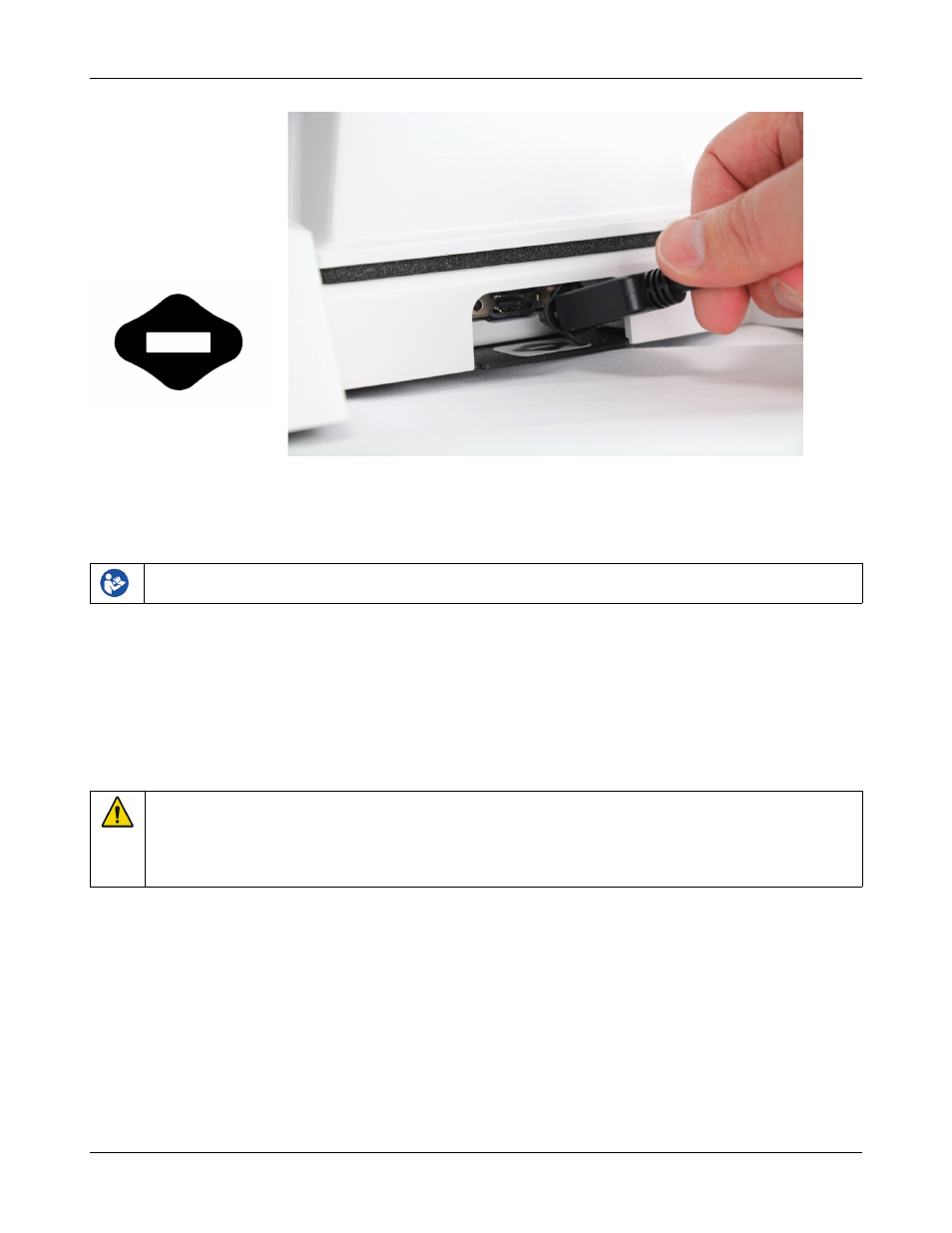
Text box cable provided uses HDMI connector, but is distinguished by a diamond-shaped marker at both ends.
IMPORTANT: Use only Audioscan-supplied cables for this purpose.
4. The Verifit can also be connected to an external monitor. Connect a video monitor (HDMI or DVI with
adapter) to the MONITOR connector on the rear connector panel.
Failure to follow operating instructions could place the user or operator at risk.
5. Open the lid of the test chamber by using your thumb to roll the rubber roller toward the front of the Verifit.
This is made easier by placing your fingers under the front lip. When sealing the chamber in its closed
position, place your fingers on top of the lid and use your thumb to roll the rubber roller toward the rear of
the Verifit.
6. Connect the Verifit power supply (included) to the power connector on the rear connector panel.
7. Connect the power cord (included) from the Verifit power supply to a GROUNDED electrical outlet. In the
USA and Canada, this outlet should be marked Hospital Grade.
WARNING: To avoid the risk of electrical shock, use only the power supply and power cord supplied with
the Verifit and connect it only to a grounded (protectively earthed) electrical outlet.
WARNING: To allow electrical power to be rapidly disconnected in the event of an emergency, position the
power supply in an accessible location so that the power cord may be quickly disconnected.
Microphone connection
1. Plug the reference microphones and the binaural coupler microphone into the connectors in the test chamber
as shown. The binaural coupler microphone is positioned in the test chamber magnetically.
21