Setting note 7, Ct performance evaluation: saturation factor – Basler Electric BE1-87T User Manual
Page 135
9171300990 Rev V
BE1-87T Setting Notes
A-7
IFs
IF
SF =
Setting Note 7
CT Performance Evaluation: Saturation Factor
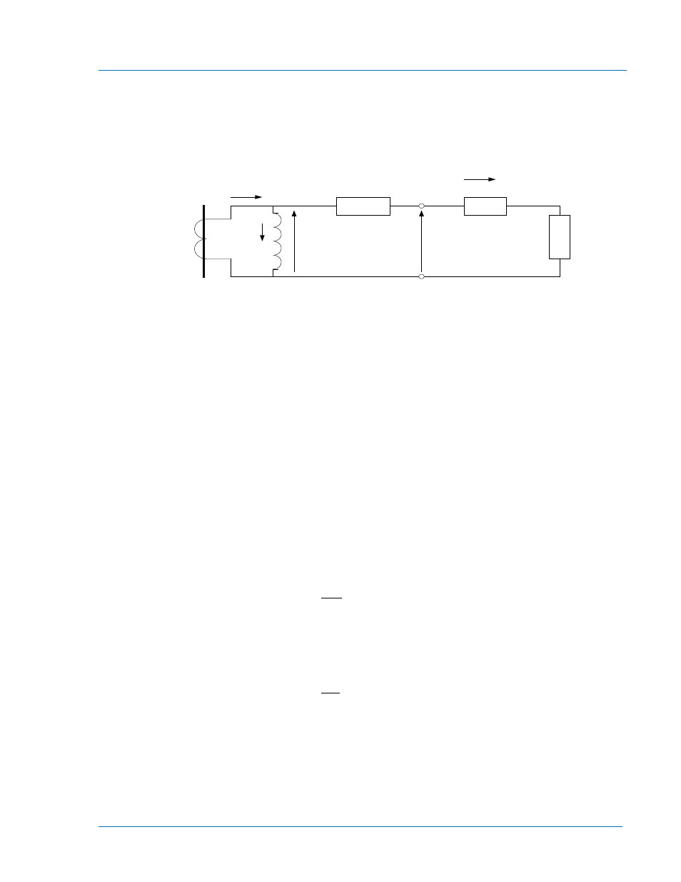
The secondary current delivered by a current transformer to a relay circuit is always less than the current
available from an ideal CT. The ideal or ratio current (
Ist=IP/RCT) is reduced by the excitation current (Ie)
to yield the actual current (
Is). This relationship is illustrated in the CT equivalent circuit shown in
Figure A-7.
Rs
Rl
Rr
Ve
VT
Is
Ie
IP
Ist
Figure A-7. CT Equivalent Circuit
For relaying applications, the CT performance is considered acceptable if the ratio correction is less than
10%. The ratio error is defined in C57.13-1993, Section 8.1.10 as
Ie/Is. This criterion is expressed in the
ANSI C accuracy class which is defined in the following sentence. Under steady state (symmetrical
current) conditions, the excitation current must be less than 10 amperes for a relay current of 100 amperes
into the specified standard burden. Since fault currents necessarily start with some degree of transient DC
offset, good design practice requires that the ratio error remain below 10% during the initial transient offset
period, if possible, particularly when fast tripping is in effect. It has been generally accepted that a design
for a saturation factor (SF) of 0.5 or less is acceptable. The following analysis provides two definitions of
the saturation factor using a C200 application as an example.
Saturation Factor Defined from the ANSI C Classification
In Figure A-8, the CT terminal voltage increases linearly with the secondary current along the V=ZBxI line
where ZB is the total CT burden (leads plus relays for a particular fault and connection). A terminal voltage
(VT) corresponds to the maximum fault current. This voltage is lower than the maximum voltage (VC) that
the C200 CT can support. Saturation will occur (i.e. ratio error will exceed 10%) for secondary currents in
excess of
IFs where the corresponding terminal voltage crosses the accuracy class limit VC (point C in
Figure A-8). We can define a measure of the degree of saturation with the saturation factor (SF):
By examination of triangles OAB and OCD, the same saturation factor can be expressed as:
VC
VT
SF =