Figure 4-28. 30° phase shift compensation jumpers – Basler Electric BE1-87T User Manual
Page 68
4-26
BE1-87T Installation
9171300990 Rev V
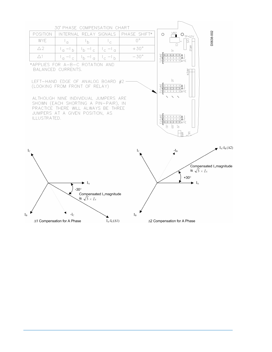
Figure 4-28. 30° Phase Shift Compensation Jumpers
The transformer in the example shown in Figure 4-28 and 4-29 has a delta connection on the primary
winding. The currents in each winding of the delta are A, B and C respectively as reflected from the wye
connected secondary winding. The delta connection of the transformer windings causes the current
flowing in the phase leads connected to the delta winding to be A-B, B-C and C-A respectively. The CT
currents on the wye side must be combined similarly to provide A-B, B-C and C-A to compensate. This is
done in Figure 4-28 by connecting the wye side CTs in delta such that the currents sent to the relay are
A-B, B-C and C-A. This is shown in Figure 4-29 by selecting phase compensation jumper position ∆2 for
the wye side input.