Checking the relay settings and system inputs, Checking the relay settings and system inputs -49, Table 4-3. single-phase input terminals – Basler Electric BE1-87T User Manual
Page 91
9171300990 Rev V
BE1-87T Installation
4-49
Checking the Relay Settings and System Inputs
Steps 1 and 2 check that the current inputs from the power transformer are correct and consistent with
the BE1-87T settings. The remaining steps check that the relay settings are within acceptable
parameters.
CAUTION
DO NOT install connection plugs, apply power, remove circuit boards, or carry
out any of the other instructions given unless you are thoroughly familiar with
the instructions in the sections on Relay Operating Precautions on page 4-1
and Relay Disassembly: Precautions on page 4-11.
Step 1. Insert the cradle assembly into the relay case, then:
Three-Phase Units with Sensing Input Type G: Remove the lower connection plug first. Then
remove the upper connection plug. Insert two Test Plugs (P/N 10095 or equivalent) in place of
the top and bottom connection plugs. For further information, refer to TEST PLUG in Section 6,
MAINTENANCE. Terminal 20 (trip output common) shown in Figure 4-10, must be isolated for
this test.
All other styles: Replace the top connection plug with a Test Plug (P/N 10095 or equivalent).
For further information, refer to TEST PLUG in Section 6, MAINTENANCE. Terminal 9 (trip
output common) shown in Figures 4-7 through 4-9 must be isolated for this test.
Step 2. Using an ammeter and phase angle meter, measure the magnitude and phase angle of each
current input, testing two inputs at a time. Begin with Inputs 1 and 2.
CAUTION
When more than two inputs are present, all inputs not being tested must be
shorted to ground.
Single-Phase Units: Relay must not trip when the current to each input (of the pair being
tested) is equal to the other in magnitude and the two currents are 180° out of phase (e.g.,
Inputs 1 and 2 measured, with Inputs 3, 4 and 5 shorted). For input terminal numbers, see
Table 4-3.
Three-Phase Units: Relay must not trip when the current to Input 1 is equal to that of Input 2 in
magnitude and the phase angle is as shown in Table 4-4. If there are three inputs per phase,
interchange Inputs 2 and 3 and repeat the procedure, this time with magnitudes and phase
angles as shown in Table 4-4. (Testing may require six synchronized current sources.)
Step 3. Using the Test Plug, reestablish all input connections and verify that the front panel REST.
TRIP and UNREST. TRIP LEDs are extinguished.
This assures that the
X TAP settings and jumper settings (refer to Figures 4-20, 4-21 and 4-27)
are within acceptable parameters and that the differential current is below pickup.
If the
REST. TRIP or UNREST. TRIP LEDs light, recheck the system current inputs and relay
settings.
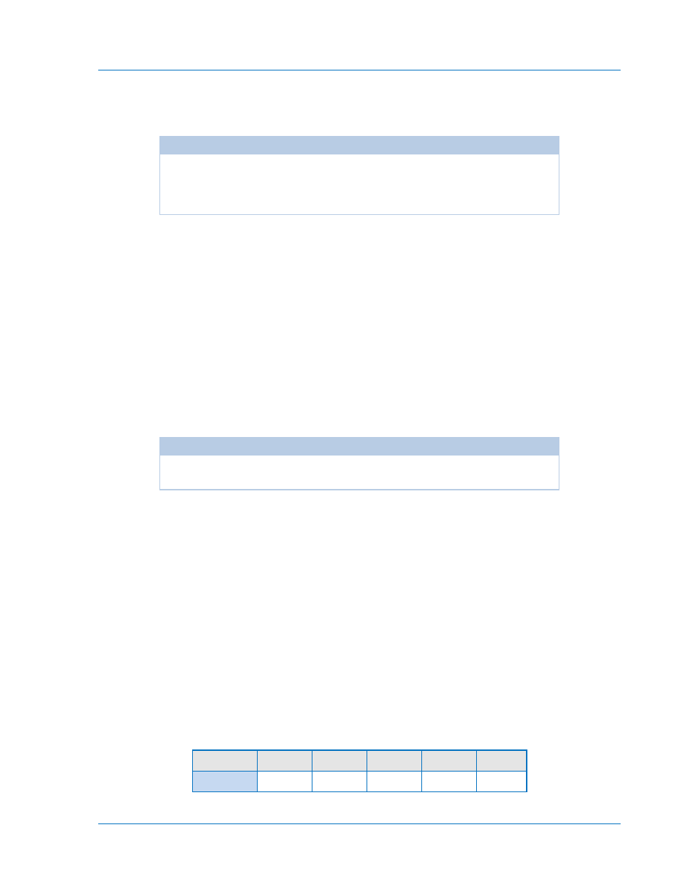
Table 4-3. Single-Phase Input Terminals
Input 1
Input 2
Input 3
Input 4 Input 5
Terminals: 11 & 13 12 & 13 14 & 13 15 & 13 16 & 13