Daktronics Venus 1500 Ver 1.x User Manual
Page 70
Appendix C:
Counters & Timers
C-3
C.5 Counter
To setup a counter, first be sure [
COUNTER
] is selected at the top of
the dialog box.
m
Note: When switching between timers and
counters on an edited item, there is no automatic save of the previous
information. A warning box appears if the previous values have not
been saved. Select [
YES
] to continue without saving or [
NO
] to cancel
the command and return to the previous screen.
C.5.1 Counter
Numbers
Three different counters can be setup for a counter file. Each of these counters creates
information that is inserted into an RTD (Real Time Data) buffer on the sign. (RTD
fields are setup in the Message Editor. Refer to Section 5.12).
Click on the desired counter number to set a counter for the file. A dot appears next to
the name of the counter to indicate it has been selected.
m
Note: When setting up
several counters (1, 2 and 3), the current counter settings are automatically saved when
the next counter is selected.
C.5.2 RTD
Information
Because the counter uses an RTD field to appear on the sign, some RTD parameters
must be setup from the Counter dialog box.
One of the primary fields is the Base Offset. This offset must be the same as that
configured in the Message Editor in the Venus 1500 software (refer to Section 5.12.1).
The base offset can only be set for Counter 1. This field is disabled for Counters 2 and
3. Click on the arrows next to the Base Offset box or highlight the number in the box
and enter the correct number to set it. The maximum value is 4,960 for DataTrac signs.
The maximum value is 1,960 for InfoNet and Galaxy signs.
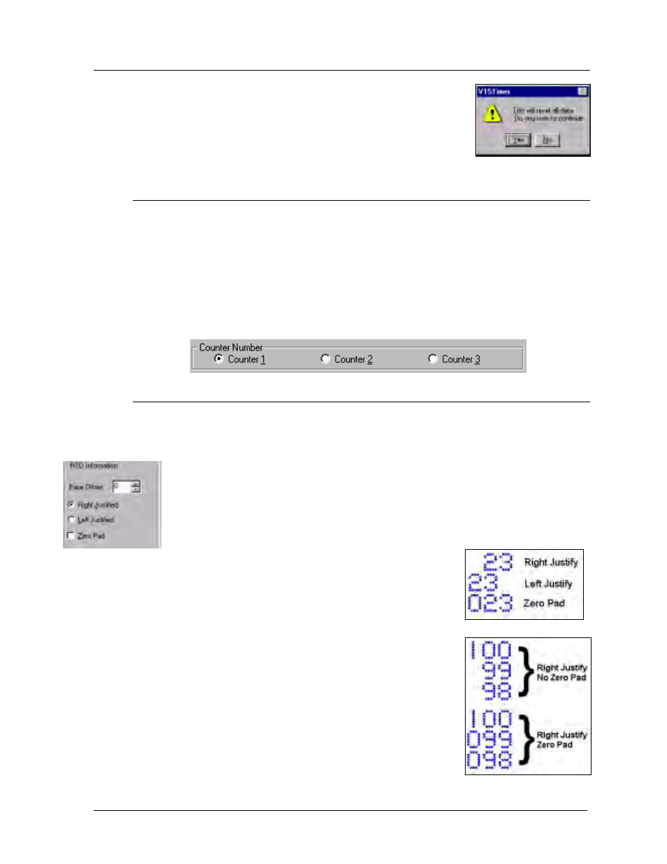
The numbers in the counter can be aligned (justified) to
either the left or the right (refer to Example 1). If right
justification is used, blank (unseen) digits are used to
maintain the length of the RTD field as the counter
progresses. Activating the Zero Pad makes these blank
digits visible with zeros (refer to Example 2).
m
Notes:
•
=
RTD offset can only be configured in the first counter.
•
=
The RTD offset must be the same as that configured in
the Venus 1500 software (refer to Section 5.12.1).
•
=
The Venus 1500 software RTD length for counters is
always 13. Therefore, if Counter 1 has an RTD offset
of zero, Counter 2’s offset is 13 and Counter 3’s offset
is 26.
•
=
Zero Pad cannot be used with Left Justify.
Example 1
Example 2