Rsvp gr configuration example, Network requirements, Configuration procedure – H3C Technologies H3C S12500-X Series Switches User Manual
Page 103
92
Min Bandwidth : - Max Bandwidth : -
Collected Bandwidth : -
# Execute the display ip routing-table command on Switch A. The output shows a static route entry with
interface Tunnel 1 as the egress interface.
RSVP GR configuration example
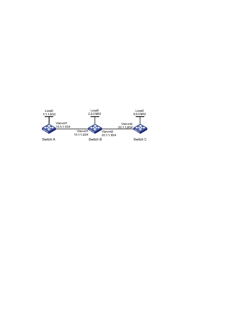
Network requirements
Switch A, Switch B, and Switch C run IS-IS.
Use RSVP-TE to establish a TE tunnel from Switch A to Switch C.
Configure RSVP GR on the switches to ensure continuous forwarding when a switch reboots.
Figure 27 Network diagram
Configuration procedure
1.
Configure IP addresses and masks for interfaces. (Details not shown.)
2.
Configure IS-IS to advertise interface addresses, including the Loopback interface address. (Details
not shown.)
3.
Configure an LSR ID, enable MPLS, MPLS TE, RSVP, and RSVP hello extension:
# Configure Switch A.
<SwitchA> system-view
[SwitchA] mpls lsr-id 1.1.1.9
[SwitchA] mpls te
[SwitchA-te] quit
[SwitchA] rsvp
[SwitchA-rsvp] quit
[SwitchA] interface vlan-interface 1
[SwitchA-Vlan-interface1] mpls enable
[SwitchA-Vlan-interface1] mpls te enable
[SwitchA-Vlan-interface1] rsvp enable
[SwitchA-Vlan-interface1] rsvp hello enable
[SwitchA-Vlan-interface1] quit
# Configure Switch B.
<SwitchB> system-view
[SwitchB] mpls lsr-id 2.2.2.9
[SwitchB] mpls te
[SwitchB-te] quit
[SwitchB] rsvp
[SwitchB-rsvp] quit