Label acceptance control configuration example, Network requirements, Configuring an lsp generation policy – H3C Technologies H3C S12500-X Series Switches User Manual
Page 45
34
100 bytes from 20.1.1.2: Sequence=2 time=1 ms
100 bytes from 20.1.1.2: Sequence=3 time=8 ms
100 bytes from 20.1.1.2: Sequence=4 time=2 ms
100 bytes from 20.1.1.2: Sequence=5 time=1 ms
--- FEC: 21.1.1.0/24 ping statistics ---
5 packets transmitted, 5 packets received, 0.0% packet loss
round-trip min/avg/max = 1/2/8 ms
# On Switch C, test the connectivity of the LDP LSP from Switch C to Switch A.
[SwitchC] ping mpls -a 21.1.1.1 ipv4 11.1.1.0 24
MPLS Ping FEC: 11.1.1.0/24 : 100 data bytes
100 bytes from 10.1.1.1: Sequence=1 time=1 ms
100 bytes from 10.1.1.1: Sequence=2 time=1 ms
100 bytes from 10.1.1.1: Sequence=3 time=1 ms
100 bytes from 10.1.1.1: Sequence=4 time=1 ms
100 bytes from 10.1.1.1: Sequence=5 time=1 ms
--- FEC: 11.1.1.0/24 ping statistics ---
5 packets transmitted, 5 packets received, 0.0% packet loss
round-trip min/avg/max = 1/1/1 ms
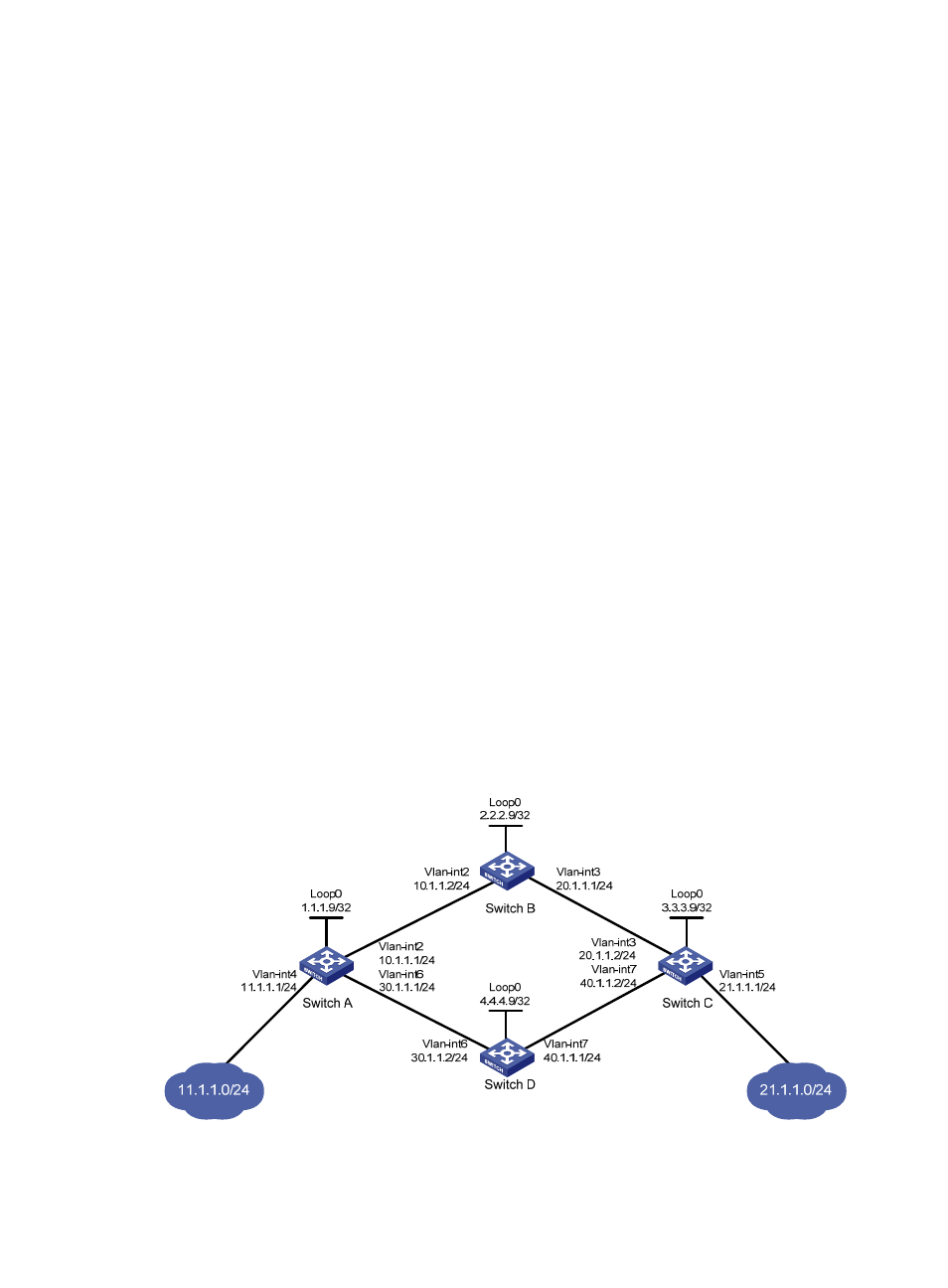
Label acceptance control configuration example
Network requirements
Two links, Switch A—Switch B—Switch C and Switch A—Switch D—Switch C, exist between subnets
11.1.1.0/24 and 21.1.1.0/24.
Configure label acceptance control, so LDP sets up LSPs only on the link Switch A—Switch B—Switch C
to forward traffic between subnets 11.1.1.0/24 and 21.1.1.0/24.
Figure 17 Network diagram