Configuration procedure – H3C Technologies H3C S12500-X Series Switches User Manual
Page 173
162
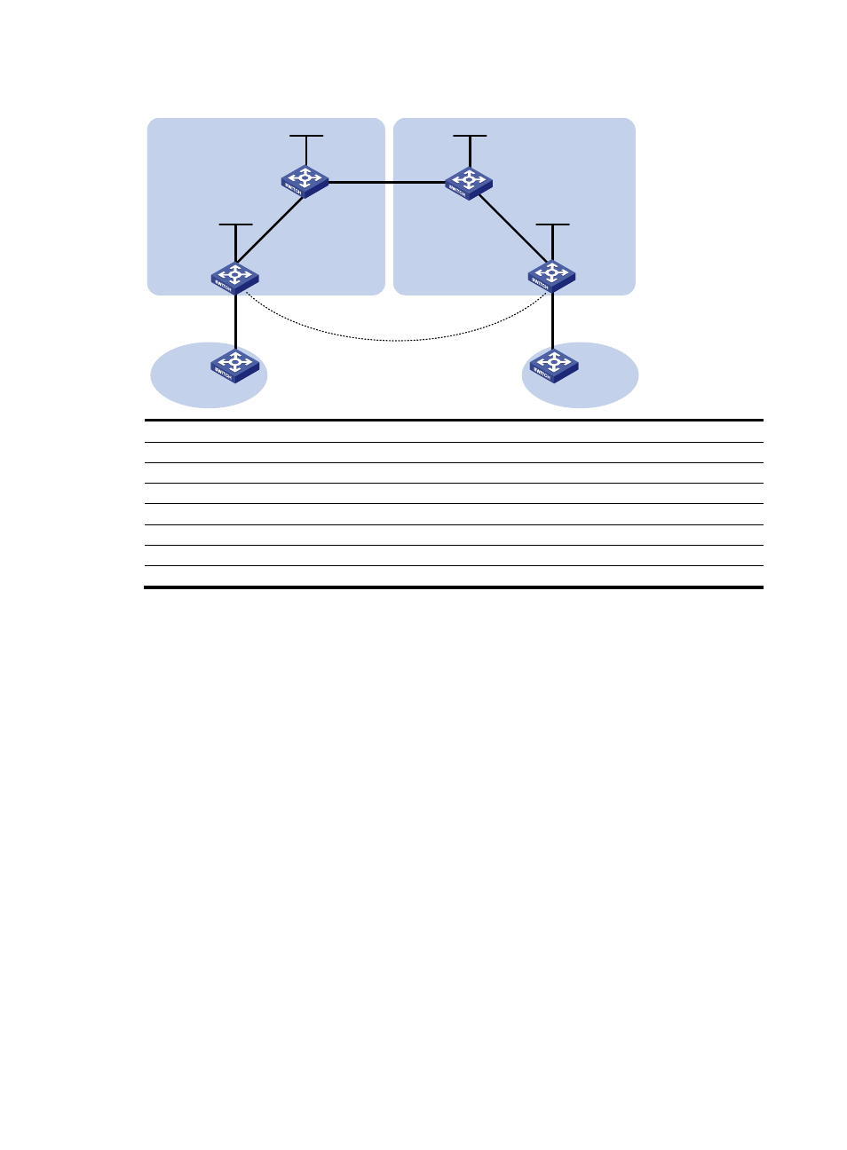
Figure 51 Network diagram
Device
Interface IP
address
Device
Interface IP
address
PE 1
Loop0
2.2.2.9/32
PE 2
Loop0 5.5.5.9/32
Vlan-int11
1.1.1.2/8
Vlan-int11 9.1.1.2/8
Vlan-int12 30.0.0.1/24
Vlan-int12 20.0.0.1/24
ASBR-PE 1
Loop0
3.3.3.9/32
ASBR-PE 2
Loop0 4.4.4.9/32
Vlan-int11
1.1.1.1/8
Vlan-int11 9.1.1.1/8
Vlan-int12 11.0.0.2/8
Vlan-int12 11.0.0.1/8
CE 1
Vlan-int12
30.0.0.2/24
CE 2
Vlan-int12 20.0.0.2/24
Configuration procedure
1.
Configure CE 1:
# Configure an IP address for VLAN-interface 12.
<CE1> system-view
[CE1] interface vlan-interface 12
[CE1-Vlan-interface12] ip address 30.0.0.2 24
[CE1-Vlan-interface12] quit
# Configure 30.0.0.1 as an EBGP peer, and redistribute direct routes.
[CE1] bgp 65001
[CE1-bgp] peer 30.0.0.1 as-number 100
[CE1-bgp] address-family ipv4 unicast
[CE1-bgp-ipv4] peer 30.0.0.1 enable
[CE1-bgp-ipv4] import-route direct
[CE1-bgp-ipv4] quit
[CE1-bgp] quit
2.
Configure PE 1:
# Configure IS-IS on PE 1.
<PE1> system-view
[PE1] isis 1
[PE1-isis-1] network-entity 10.111.111.111.111.00
[PE1-isis-1] quit
PE 1
MPLS backbone
MPLS backbone
ASBR-PE 1
ASBR-PE 2
Vlan-int11
Vlan-int11
Vlan-int11
Loop0
Loop0
Loop0
Loop0
PE 2
Site 1
Site 2
MP-EBGP
AS 100
AS 600
Vlan-int12
Vlan-int12
Vlan-int11
CE 1
CE 2
Site 1
Site 2
Vlan-int12
Vlan-int12
Vlan-int12
Vlan-int12