Configuration procedure, Protocols and standards, Mpls te configuration task list – H3C Technologies H3C S12500-X Series Switches User Manual
Page 74
63
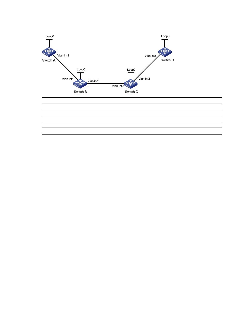
Figure 22 Network diagram
Device Interface IP
address
Device
Interface
IP address
Switch A
Loop0
1.1.1.9/32
Switch D
Loop0
4.4.4.9/32
Vlan-int1
10.1.1.1/24
Vlan-int3
30.1.1.2/24
Switch B
Loop0
2.2.2.9/32
Switch C
Loop0
3.3.3.9/32
Vlan-int1
10.1.1.2/24
Vlan-int3
30.1.1.1/24
Vlan-int2
20.1.1.1/24
Vlan-int2
20.1.1.2/24
Configuration procedure
1.
Configure IP addresses and masks for interfaces. (Details not shown.)
2.
Configure IS-IS to advertise interface addresses, including the Loopback interface address.
For more information, see "
Establishing an MPLS TE tunnel with RSVP-TE
3.
Configure an LSR ID, and enable MPLS, MPLS TE, and RSVP-TE on each switch, and configure
Switch A and Switch D to assign a non-null label to the penultimate hop:
# Configure Switch A.
<SwitchA> system-view
[SwitchA] mpls lsr-id 1.1.1.9
[SwitchA] mpls label advertise non-null
[SwitchA] mpls te
[SwitchA-te] quit
[SwitchA] rsvp
[SwitchA-rsvp] quit
[SwitchA] interface vlan-interface 1
[SwitchA-Vlan-interface1] mpls enable
[SwitchA-Vlan-interface1] mpls te enable
[SwitchA-Vlan-interface1] rsvp enable
[SwitchA-Vlan-interface1] quit
# Configure Switch B.
<SwitchB> system-view
[SwitchB] mpls lsr-id 2.2.2.9
[SwitchB] mpls te
[SwitchB-te] quit
[SwitchB] rsvp
[SwitchB-rsvp] quit
[SwitchB] interface vlan-interface 1