Configuration procedure – H3C Technologies H3C S12500-X Series Switches User Manual
Page 245
234
•
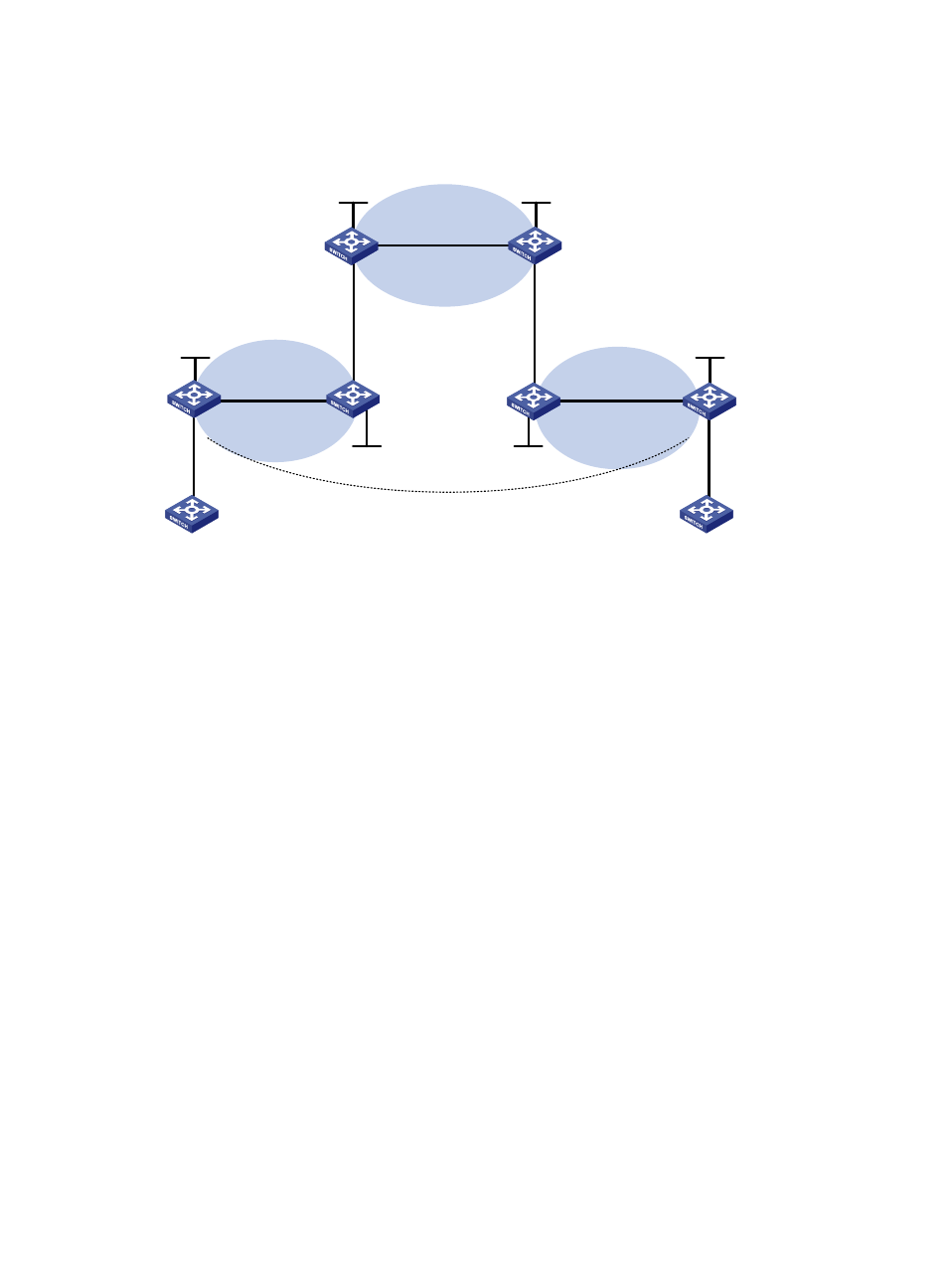
Exchange of the end customers' internal routes between PE 3 and PE 4, the PEs of the customer
carrier. An MP-IBGP peer relationship must be established between PE 3 and PE 4.
Figure 62 Network diagram
Configuration procedure
1.
Configure MPLS L3VPN on the provider carrier backbone. Enable IS-IS as the IGP, enable LDP on
PE 1 and PE 2, and establish an MP-IBGP peer relationship between the PEs:
# Configure PE 1.
<PE1> system-view
[PE1] interface loopback 0
[PE1-LoopBack0] ip address 3.3.3.9 32
[PE1-LoopBack0] quit
[PE1] mpls lsr-id 3.3.3.9
[PE1] mpls ldp
[PE1-ldp] quit
[PE1] isis 1
[PE1-isis-1] network-entity 10.0000.0000.0000.0004.00
[PE1-isis-1] quit
[PE1] interface loopback 0
[PE1-LoopBack0] isis enable 1
[PE1-LoopBack0] quit
[PE1] interface vlan-interface 12
[PE1-Vlan-interface12] ip address 30.1.1.1 24
[PE1-Vlan-interface12] isis enable 1
[PE1-Vlan-interface12] mpls enable
[PE1-Vlan-interface12] mpls ldp enable
[PE1-Vlan-interface12] mpls ldp transport-address interface
[PE1-Vlan-interface12] quit
[PE1] bgp 100
[PE1-bgp] peer 4.4.4.9 as-number 100
[PE1-bgp] peer 4.4.4.9 connect-interface loopback 0
PE 1
PE 2
Provider carrier
Customer carrier
PE 4
CE 2
CE 1
PE 3
CE 3
CE 4
AS 65410
AS 65420
Loop0
Loop0
Loop0
Customer carrier
Vlan-int11
Loop0
Loop0
AS 100
AS 100
Vlan-int11
Vlan-int12
Vlan-int12
Vlan-int11
Vlan-int11
Vlan-int12
Vlan-int12
Vlan-int11
Vlan-int11
Vlan-int12
Vlan-int12
Vlan-int11
Vlan-int11
MP-IBGP