Configuring hovpn, Network requirements, Configuration procedure – H3C Technologies H3C S12500-X Series Switches User Manual
Page 196
185
Configuring HoVPN
Network requirements
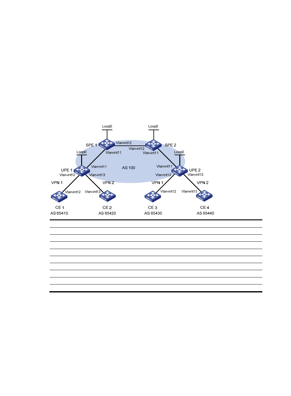
There are two levels of networks, the backbone and the MPLS VPN networks, as shown in
.
•
SPEs act as PEs to allow MPLS VPNs to access the backbone.
•
UPEs act as PEs of the MPLS VPNs to allow end users to access the VPNs.
•
Performance requirements for the UPEs are lower than those for the SPEs.
•
SPEs advertise routes permitted by the routing policies to UPEs, permitting CE 1 and CE 3 in VPN
1 to communicate with each other, and forbidding CE 2 and CE 4 in VPN 2 to communicate with
each other.
Figure 54 Network diagram
Device
Interface
IP address
Device
Interface
IP address
CE 1
Vlan-int12
10.2.1.1/24
CE 3
Vlan-int12 10.1.1.1/24
CE 2
Vlan-int13
10.4.1.1/24
CE 4
Vlan-int13 10.3.1.1/24
UPE 1
Loop0
1.1.1.9/32
UPE 2
Loop0
4.4.4.9/32
Vlan-int11
172.1.1.1/24
Vlan-int11 172.2.1.1/24
Vlan-int12
10.2.1.2/24
Vlan-int12 10.1.1.2/24
Vlan-int13
10.4.1.2/24
Vlan-int13
10.3.1.2/24
SPE 1
Loop0
2.2.2.9/32
SPE 2
Loop0
3.3.3.9/32
Vlan-int11
172.1.1.2/24
Vlan-int11 172.2.1.2/24
Vlan-int12
180.1.1.1/24
Vlan-int12
180.1.1.2/24
Configuration procedure
1.
Configure UPE 1:
# Configure basic MPLS and MPLS LDP to establish LDP LSPs.
<UPE1> system-view
[UPE1] interface loopback 0
[UPE1-LoopBack0] ip address 1.1.1.9 32
[UPE1-LoopBack0] quit
[UPE1] mpls lsr-id 1.1.1.9
[UPE1] mpls ldp