Configuring ldp pw redundancy, Network requirements, Configuration procedure – H3C Technologies H3C S12500-X Series Switches User Manual
Page 277: Configuring inter-as ipv6 vpn option c
266
Flags: M - main, B - backup, H - hub link, S - spoke link, N - no split horizon
Total number of PWs: 1, 1 up, 0 blocked, 0 down, 0 defect
Xconnect-group Name: vpnb
Peer PW ID/Rmt Site In/Out Label Proto Flag Link ID State
192.2.2.2 1 65663/65665 BGP M 1 Up
# CE 1 and CE 2 can ping each other.
Configuring LDP PW redundancy
Network requirements
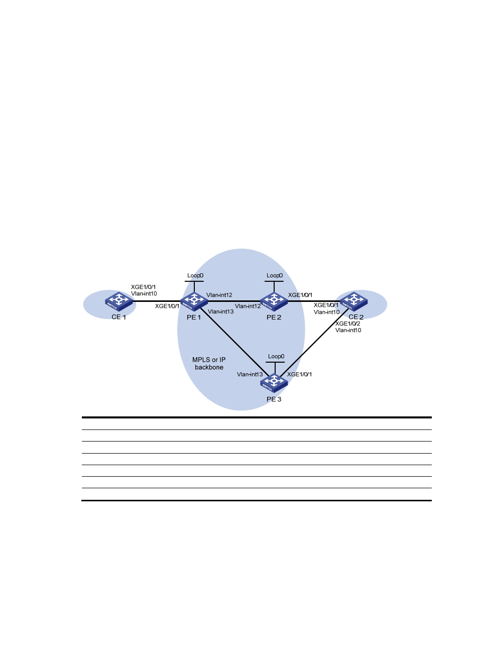
Create two LDP PWs to implement PW redundancy between CE 1 and CE 2. The primary PW goes
through PE 1—PE 2. The backup PW goes through PE 1—PE 3. When the primary PW fails, CE 1 and
CE 2 communicate through the backup PW.
Figure 71 Network diagram
Device Interface IP
address
Device
Interface
IP address
CE 1
Vlan-int10
100.1.1.1/24
PE 2
Loop0
2.2.2.2/32
PE 1
Loop0
1.1.1.1/32
Vlan-int10 -
Vlan-int10
-
Vlan-int12 12.1.1.2/24
Vlan-int12
12.1.1.1/24
PE
3
Loop0
3.3.3.3/32
Vlan-int13
13.1.1.1/24
Vlan-int10 -
CE 2
Vlan-int10
100.1.1.2/24
Vlan-int13 13.1.1.3/24
Configuration procedure
Before you perform the following configurations, configure VLANs and add ports to VLANs on switches.
1.
Configure CE 1:
<CE1> system-view
[CE1] interface vlan-interface 10
[CE1-Vlan-interface10] ip address 100.1.1.1 24
[CE1-Vlan-interface10] quit