Configuration procedure, Creating a sham link – H3C Technologies H3C S12500-X Series Switches User Manual
Page 187
176
•
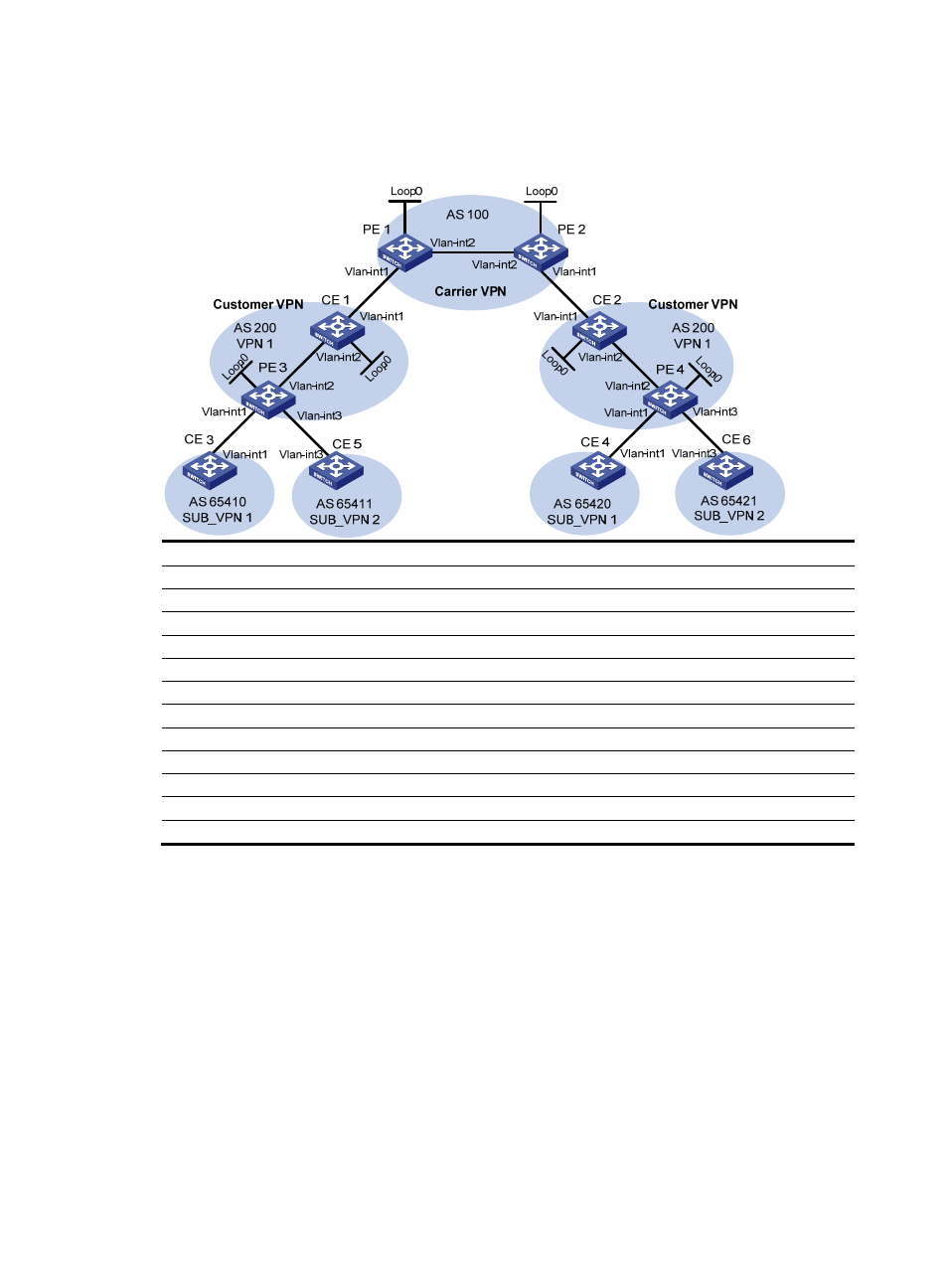
To implement exchange of sub-VPN routes between customer PEs and service provider PEs,
MP-EBGP peers must be established between service provider PEs and customer CEs.
Figure 53 Network diagram
Device Interface IP
address
Device
Interface
IP address
CE 1
Loop0
2.2.2.9/32
CE 2
Loop0
5.5.5.9/32
Vlan-int2
10.1.1.2/24
Vlan-int1
21.1.1.2/24
Vlan-int1
11.1.1.1/24
Vlan-int2
20.1.1.1/24
CE 3
Vlan-int1
100.1.1.1/24
CE 4
Vlan-int1
120.1.1.1/24
CE 5
Vlan-int3
110.1.1.1/24
CE 6
Vlan-int3
130.1.1.1/24
PE 1
Loop0
3.3.3.9/32
PE 2
Loop0
4.4.4.9/32
Vlan-int1
11.1.1.2/24
Vlan-int1
21.1.1.1/24
Vlan-int2
30.1.1.1/24
Vlan-int2
30.1.1.2/24
PE 3
Loop0
1.1.1.9/32
PE 4
Loop0
6.6.6.9/32
Vlan-int1
100.1.1.2/24
Vlan-int1
120.1.1.2/24
Vlan-int2
10.1.1.1/24
Vlan-int2
20.1.1.2/24
Vlan-int3
110.1.1.2/24
Vlan-int3
130.1.1.2/24
Configuration procedure
1.
Configure MPLS L3VPN on the service provider backbone. Use IS-IS as the IGP protocol, enable
LDP, and establish an MP-IBGP peer relationship between PE 1 and PE 2:
# Configure PE 1.
<PE1> system-view
[PE1] interface loopback 0
[PE1-LoopBack0] ip address 3.3.3.9 32
[PE1-LoopBack0] quit
[PE1] mpls lsr-id 3.3.3.9
[PE1] mpls ldp
[PE1-ldp] quit
[PE1] isis 1
[PE1-isis-1] network-entity 10.0000.0000.0000.0004.00