Configuring an intra-domain multi-segment pw, Network requirements – H3C Technologies H3C S12500-X Series Switches User Manual
Page 282
271
1.1.1.1 20 65650/65662 LDP M 1 Up
# Display L2VPN PW information on PE 3. The output shows that an LDP PW has been established.
[PE3] display l2vpn pw
Flags: M - main, B - backup, H - hub link, S - spoke link, N - no split horizon
Total number of PWs: 1, 1 up, 0 blocked, 0 down, 0 defect
Xconnect-group Name: vpna
Peer PW ID In/Out Label Proto Flag Link ID State
1.1.1.1 30 65655/65669 LDP M 1 Up
# CE 1 and CE 2 can ping each other.
# Manually switch to the backup PW on PE 1.
<PE1> l2vpn switchover peer 2.2.2.2 pw-id 20
# Display L2VPN PW information on PE 1. The output shows that the PW switchover is successful.
<PE1> display l2vpn pw
Flags: M - main, B - backup, H - hub link, S - spoke link, N - no split horizon
Total number of PWs: 2, 1 up, 1 blocked, 0 down, 0 defect
Xconnect-group Name: vpna
Peer PW ID In/Out Label Proto Flag Link ID State
2.2.2.2 20 65662/65660 LDP M 1 Blocked
3.3.3.3 30 65659/65655 LDP B 1 Up
# CE 1 and CE 2 can ping each other.
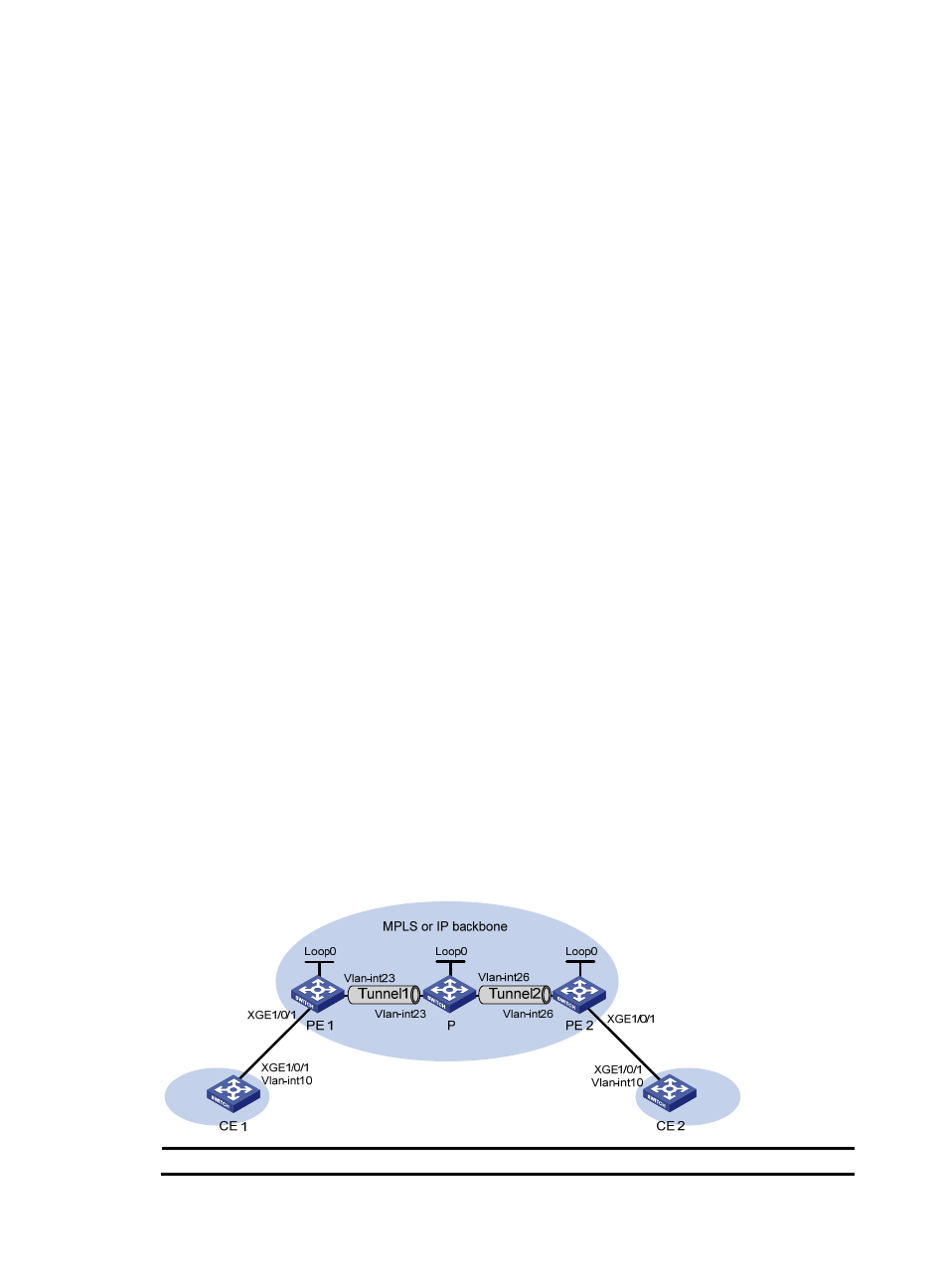
Configuring an intra-domain multi-segment PW
Network requirements
As shown in
, there is no public tunnel between PE 1 and PE 2, and there is an MPLS TE tunnel
between PE 1 and P, and an MPLS TE tunnel between P and PE 2. Configure a multi-segment PW
between PE 1 and PE 2, so CE 1 and CE 2 can communicate over the backbone. The multi-segment PW
includes an LDP PW between PE 1 and P, and a static PW between P and PE 2. The two PWs are
connected on P.
Figure 72 Network diagram
Device
Interface
IP address
Device
Interface
IP address