Ldp pw configuration example, Network requirements, Configuration procedure – H3C Technologies H3C S12500-X Series Switches User Manual
Page 309: Configuring mpls l2vpn, Overview, Basic concepts of mpls l2vpn
298
Tunnel Group ID : 0x1800000760000006
Tunnel NHLFE IDs : 132
LDP PW configuration example
Network requirements
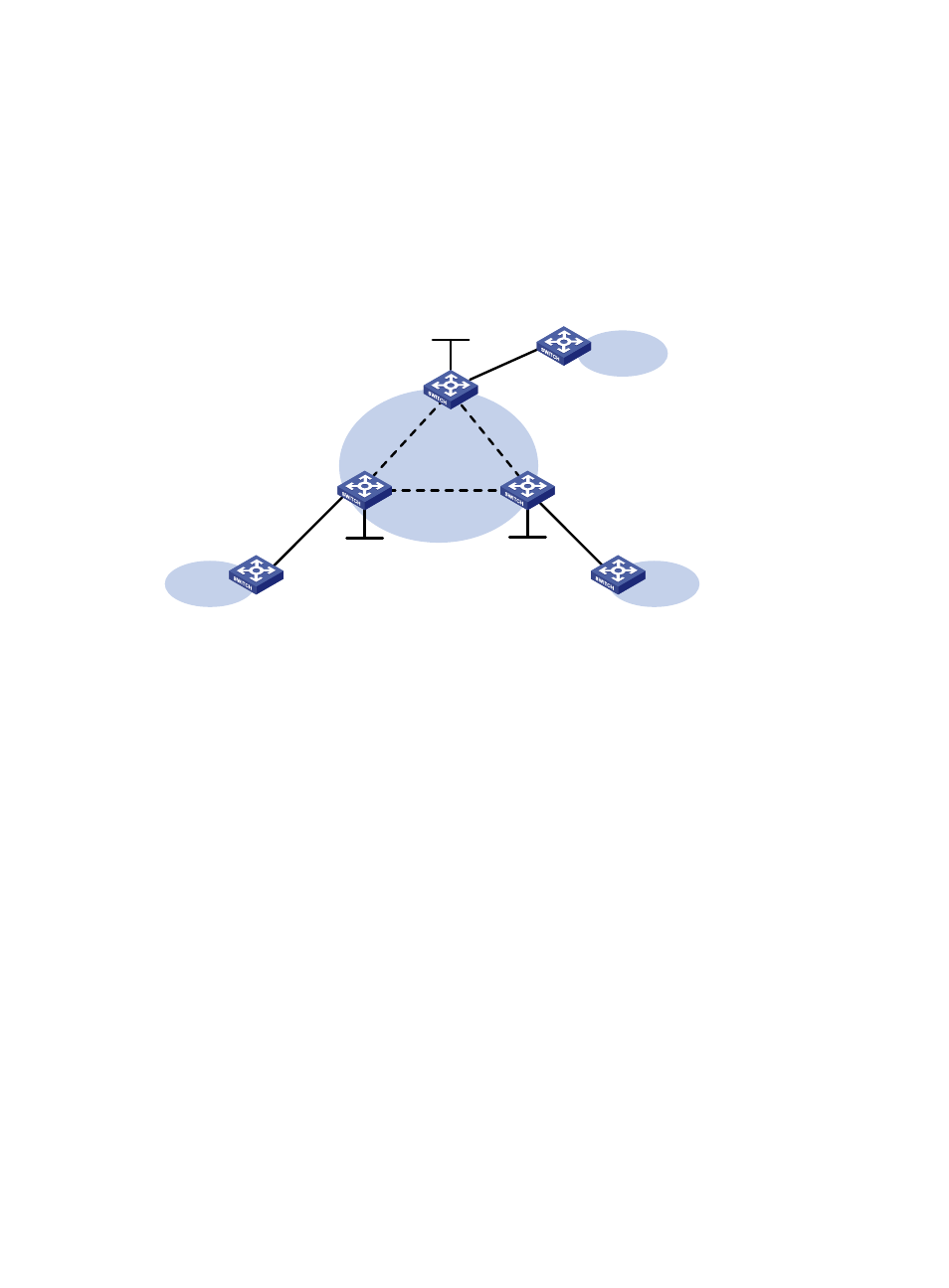
Configure VPLS on each PE, and establish LDP PWs between the PEs to interconnect the CEs.
Figure 77 Network diagram
Configuration procedure
1.
Configure an IGP and public tunnels on each PE. (Details not shown.)
2.
Configure PE 1:
# Configure basic MPLS.
<PE1> system-view
[PE1] interface loopback 0
[PE1-LoopBack0] ip address 1.1.1.9 32
[PE1-LoopBack0] quit
[PE1] mpls lsr-id 1.1.1.9
[PE1] mpls ldp
[PE1-ldp] quit
# Enable L2VPN.
[PE1] l2vpn enable
# Configure VSI aaa that uses LDP as the PW signaling protocol, and establish a PW to PE 2 and
PE 3, respectively.
[PE1] vsi aaa
[PE1-vsi-aaa] pwsignaling ldp
[PE1-vsi-aaa-ldp] peer 2.2.2.9 pw-id 500
[PE1-vsi-aaa-ldp-2.2.2.9-500] quit
[PE1-vsi-aaa-ldp] peer 3.3.3.9 pw-id 500
[PE1-vsi-aaa-ldp-3.3.3.9-500] quit
[PE1-vsi-aaa-ldp] quit
[PE1-vsi-aaa] quit
Loop0
1.1.1.9/32
XGE1/0/1
XGE1/0/1
CE 1
VPN 1
PE 1
PE 2
Loop0
2.2.2.9/32
CE 2
VPN 1
Loop0
3.3.3.9/32
PE 3
CE 3
VPN 1
XGE1/0/1
Vlan-int20
Vlan-int20
Vlan-int30
Vlan-int30
Vlan-int40
Vlan-int40