Configuration procedure – H3C Technologies H3C S12500-X Series Switches User Manual
Page 305
294
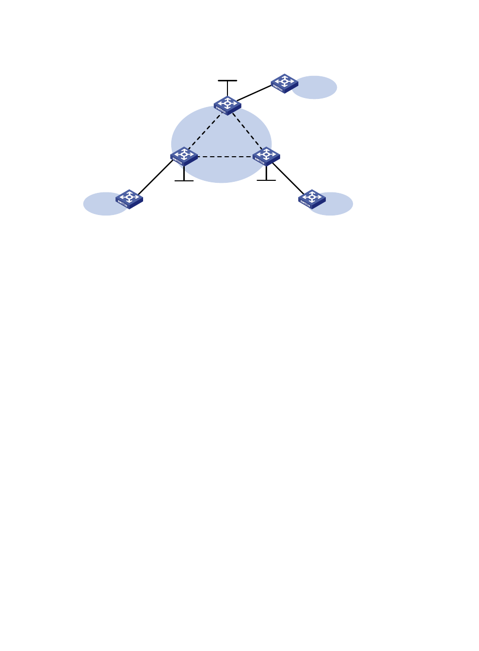
Figure 76 Network diagram
Configuration procedure
This task includes the following configurations:
•
Configure basic MPLS on each PE: configure LSR ID, enable LDP, run IGP (OSPF in this example) to
establish LSPs.
•
Establish static PWs: enable L2VPN, create static PWs, and specify labels.
1.
Configure PE 1:
# Configure an LSR ID.
<PE1> system-view
[PE1] interface loopback 0
[PE1-LoopBack0] ip address 1.1.1.9 32
[PE1-LoopBack0] quit
[PE1] mpls lsr-id 1.1.1.9
# Enable L2VPN.
[PE1] l2vpn enable
# Enable global LDP.
[PE1] mpls ldp
[PE1-ldp] quit
# Configure VLAN-interface 20 connected to PE 2 and enable LDP on the interface.
[PE1] interface vlan-interface 20
[PE1-Vlan-interface20] ip address 20.1.1.1 24
[PE1-Vlan-interface20] mpls enable
[PE1-Vlan-interface20] mpls ldp enable
[PE1-Vlan-interface20] quit
# Configure VLAN-interface 30 connected to PE 3 and enable LDP on the interface.
[PE1] interface vlan-interface 30
[PE1-Vlan-interface30] ip address 30.1.1.1 24
[PE1-Vlan-interface30] mpls enable
[PE1-Vlan-interface30] mpls ldp enable
[PE1-Vlan-interface30] quit
# Configure OSPF on PE 1 for LDP to create LSPs.
Loop0
1.1.1.9/32
XGE1/0/1
XGE1/0/1
CE 1
VPN 1
PE 1
PE 2
Loop0
2.2.2.9/32
CE 2
VPN 1
Loop0
3.3.3.9/32
PE 3
CE 3
VPN 1
XGE1/0/1
Vlan-int20
Vlan-int20
Vlan-int30
Vlan-int30
Vlan-int40
Vlan-int40