Configuring a bgp pw, Network requirements, Configuration procedure – H3C Technologies H3C S12500-X Series Switches User Manual
Page 273: Configuring bgp vpnv6 route control
262
Configuring a BGP PW
Network requirements
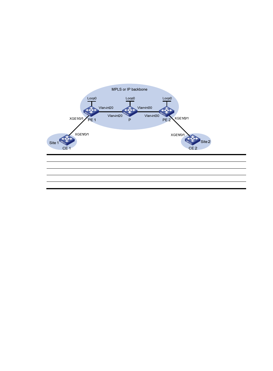
Create a BGP PW between PE 1 and PE 2 so VLAN 10 on CE 1 can communicate with VLAN 10 on CE
2.
Figure 70 Network diagram
Device Interface IP
address
Device
Interface
IP address
PE 1
Loop0
192.2.2.2/32
P
Loop0
192.4.4.4/32
Vlan-int20
10.1.1.1/24
Vlan-int20 10.1.1.2/24
PE 2
Loop0
192.3.3.3/32
Vlan-int30 10.2.2.2/24
Vlan-int30
10.2.2.1/24
Configuration procedure
Before you perform the following configurations, configure VLANs and add ports to VLANs on switches.
1.
Configure CE 1.
<CE1> system-view
[CE1] interface ten-gigabitethernet 1/0/1
[CE1-Ten-GigabitEthernet1/0/1] port link-type trunk
[CE1-Ten-GigabitEthernet1/0/1] port trunk permit vlan 10
[CE1-Ten-GigabitEthernet1/0/1] quit
2.
Configure PE 1:
# Configure an LSR ID.
<PE1> system-view
[PE1] interface loopback 0
[PE1-LoopBack0] ip address 192.2.2.2 32
[PE1-LoopBack0] quit
[PE1] mpls lsr-id 192.2.2.2
# Enable L2VPN.
[PE1] l2vpn enable
# Enable LDP globally.
[PE1] mpls ldp
[PE1-ldp] quit
# Configure VLAN-interface 20 (the interface connected to P), and enable LDP on the interface.