Mce configuration examples, Network requirements, Configuration procedure – H3C Technologies H3C S12500-X Series Switches User Manual
Page 338
327
MCE configuration examples
Configuring the MCE that uses OSPF to advertise VPN routes to
the PE
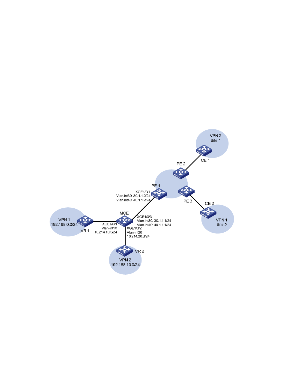
Network requirements
As shown in
, the MCE device is connected to VPN 1 through VLAN-interface 10 and is
connected with VPN 2 through VLAN-interface 20. RIP runs in VPN 2.
Configure the MCE device to separate routes from different VPNs and to advertise the VPN routes to PE
1 through OSPF.
Figure 83 Network diagram
Configuration procedure
Assume that the system name of the MCE device is MCE, the system names of the edge devices of VPN
1 and VPN 2 are VR1 and VR2, and the system name of PE 1 is PE1.
1.
Configure the VPN instances on the MCE and PE 1:
# On the MCE, configure VPN instances vpn1 and vpn2, and specify an RD and route targets for
each VPN instance.
<MCE> system-view
[MCE] ip vpn-instance vpn1
[MCE-vpn-instance-vpn1] route-distinguisher 10:1
[MCE-vpn-instance-vpn1] vpn-target 10:1