Fast detection configuration example, Network requirements, Configuration procedure – H3C Technologies H3C S10500 Series Switches User Manual
Page 101
92
[DeviceB-rrpp-ring-group1] domain 2 ring 2
[DeviceB-rrpp-ring-group1] domain 1 ring 3
# Create RRPP ring group 1 on Device C, and add subrings 2 and 3 to the RRPP ring group.
[DeviceC] rrpp ring-group 1
[DeviceC-rrpp-ring-group1] domain 2 ring 2
[DeviceC-rrpp-ring-group1] domain 1 ring 3
8.
Verify the configuration.
Use the display command to view RRPP configuration and operational information on each device.
Fast detection configuration example
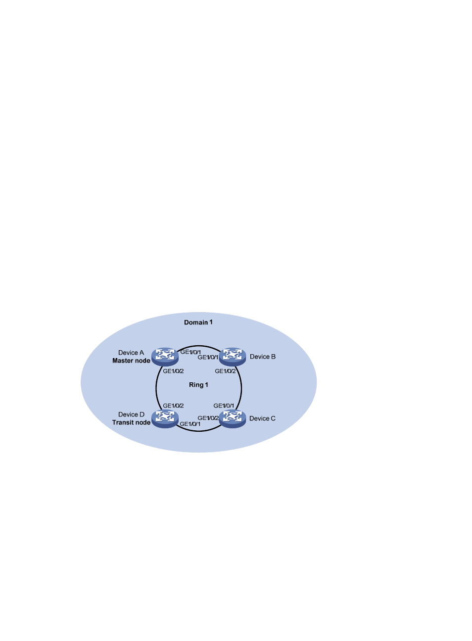
Network requirements
As shown in
,
•
Device A, Device B, Device C, and Device D constitute RRPP domain 1, VLAN 4092 is the primary
control VLAN of RRPP domain 1, and RRPP domain 1 protects VLANs 1 through 30.
•
Device A is the master node and supports RRPP fast detection; Device D is a transit node; Device B
and Device C do not support RRPP.
As neither Device B nor Device C supports RRPP, when the link between them fails, the link failure cannot
be detected by the master node timely. Configure RRPP fast detection to implement fast link switchover
even when the link between Device B and Device C fails.
Figure 24 Network diagram for fast detection configuration
Configuration procedure
1.
Configure Device A.
# Create VLANs 1 through 30, map these VLANs to MSTI 1, and activate the MST region configuration.
<DeviceA> system-view
[DeviceA] vlan 1 to 30
[DeviceA] stp region-configuration
[DeviceA-mst-region] instance 1 vlan 1 to 30
[DeviceA-mst-region] active region-configuration
[DeviceA-mst-region] quit