Network requirements, Configuration procedure – H3C Technologies H3C S10500 Series Switches User Manual
Page 198
189
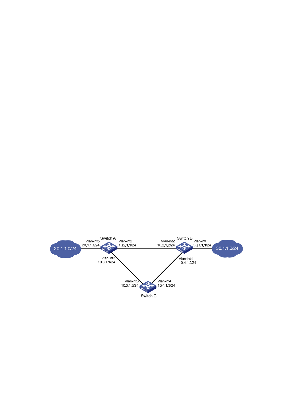
Static routing-Track-BFD collaboration configuration example
Network requirements
As shown in
, Switch A, Switch B, and Switch C are connected to two segments 20.1.1.0/24
and 30.1.1.0/24. Configure static routes on these routers so that the two segments can communicate with
each other, and configure route backup to improve reliability of the network.
Switch A is the default gateway of the hosts in segment 20.1.1.0/24. Two static routes to 30.1.1.0/24 exist
on Switch A, with the next hop being Switch B and Switch C respectively. These two static routes back up
each other as follows:
•
The static route with Switch B as the next hop has a higher priority and is the master route. If this
route is available, Switch A forwards packets to 30.1.1.0/24 through Switch B.
•
The static route with Switch C as the next hop acts as the backup route.
•
Configure static routing-track-BFD collaboration to determine whether the master route is available
in real time. If the master route is unavailable, BFD can quickly detect the route failure to make the
backup route take effect, and Switch A forwards packets to 30.1.1.0/24 through Switch C and
Switch B.
Similarly, Switch B is the default gateway of the hosts in segment 30.1.1.0/24. Two static routes to
20.1.1.0/24 exist on Switch B, with the next hop being Switch A and Switch C respectively. These two
static routes back up each other as follows:
•
The static route with Switch A as the next hop has a higher priority and is the master route. If this
route is available, Switch B forwards packets to 20.1.1.0/24 through Switch A.
•
The static route with Switch C as the next hop acts as the backup route.
•
Configure static routing-track-BFD collaboration to determine whether the master route is available
in real time. If the master route is unavailable, BFD can quickly detect the route failure to make the
backup route take effect, and Switch B forwards packets to 20.1.1.0/24 through Switch C and
Switch A.
Figure 51 Network diagram for static routing-track-BFD collaboration configuration
Configuration procedure
1.
Create VLANs, and assign corresponding ports to the VLANs. Configure the IP address of each
. (Details not shown)
2.
Configure Switch A.
# Configure a static route to 30.1.1.0/24, with the address of the next hop as 10.2.1.2 and the default
priority 60. This static route is associated with track entry 1.
<SwitchA> system-view