Configuration procedure – H3C Technologies H3C S10500 Series Switches User Manual
Page 202
193
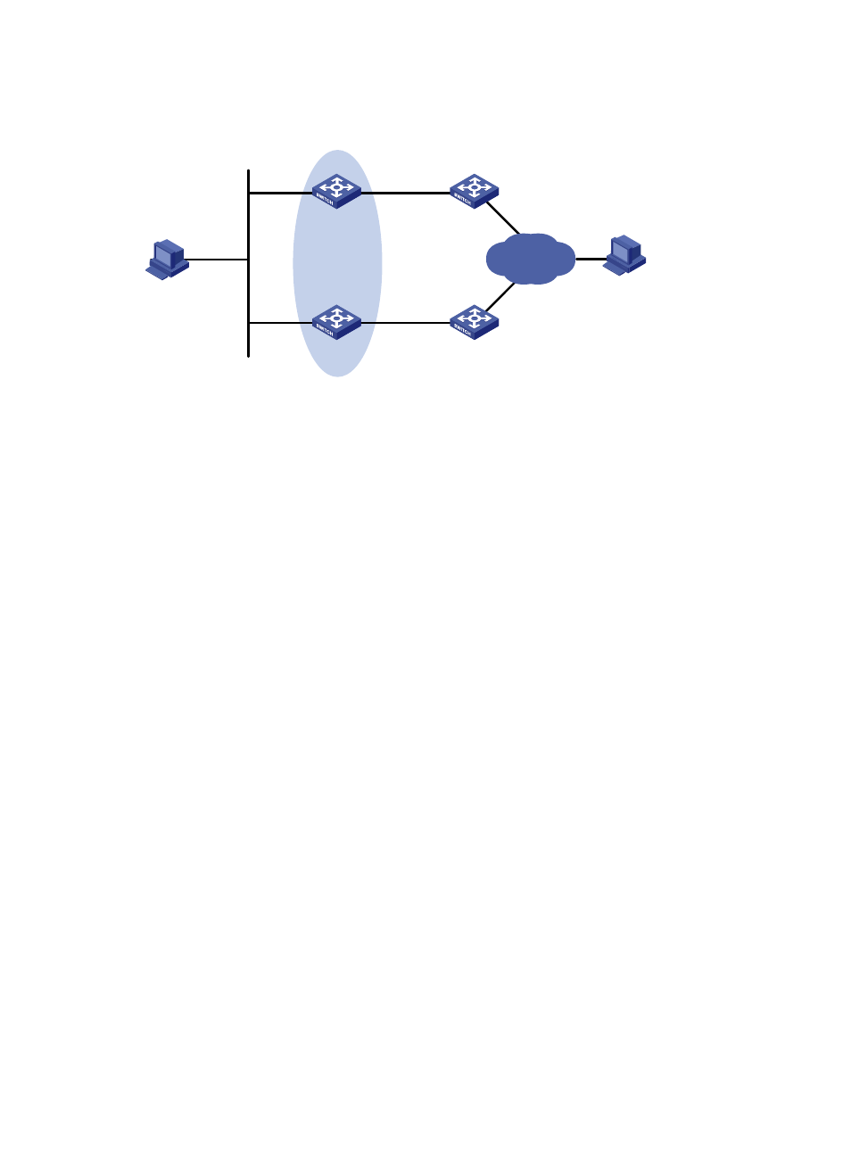
Figure 52 Network diagram for VRRP-track-interface management collaboration configuration
Host A
Switch A
Switch B
Virtual IP address:
10.1.1.10/24
Vlan-int2
10.1.1.1/24
Vlan-int2
10.1.1.2/24
Host B
10.1.1.3/24
20.1.1.1/24
Internet
Vlan-int3
10.1.2.1/24
Vlan-int3
10.1.3.1/24
Vlan-int3
10.1.3.2/24
Vlan-int3
10.1.2.2/24
Switch C
Switch D
Configuration procedure
1.
Create VLANs, and assign corresponding ports to the VLANs. Configure the IP address of each
. (Details not shown)
2.
Configure a track entry on Switch A.
# Configure track entry 1, and associate it with the physical status of the uplink interface VLAN-interface
3.
[SwitchA] track 1 interface vlan-interface 3
3.
Configure VRRP on Switch A.
# Create VRRP group 1, and configure the virtual IP address 10.1.1.10 for the group.
[SwitchA] interface vlan-interface 2
[SwitchA-Vlan-interface2] vrrp vrid 1 virtual-ip 10.1.1.10
# Set the priority of Switch A in VRRP group 1 to 110.
[SwitchA-Vlan-interface2] vrrp vrid 1 priority 110
# Configure to monitor track entry 1, and specify the priority decrement as 30.
[SwitchA-Vlan-interface2] vrrp vrid 1 track 1 reduced 30
4.
Configure VRRP on Switch B.
<SwitchB> system-view
[SwitchB] interface vlan-interface 2
# Create VRRP group 1, and configure the virtual IP address 10.1.1.10 for the group.
[SwitchB-Vlan-interface2] vrrp vrid 1 virtual-ip 10.1.1.10
5.
Verify the configuration.
After configuration, ping Host B on Host A, and you can see that Host B is reachable. Use the display
vrrp command to view the configuration result.
# Display detailed information about VRRP group 1 on Switch A.
[SwitchA-Vlan-interface2] display vrrp verbose
IPv4 Standby Information:
Run Mode : Standard
Run Method : Virtual MAC
Total number of virtual routers : 1