Networking requirements, Configuration procedure – H3C Technologies H3C S10500 Series Switches User Manual
Page 93
84
9.
Verify the configuration.
Use the display command to view RRPP configuration and operational information on each device.
Intersecting-ring load balancing configuration example
Networking requirements
As shown in
,
•
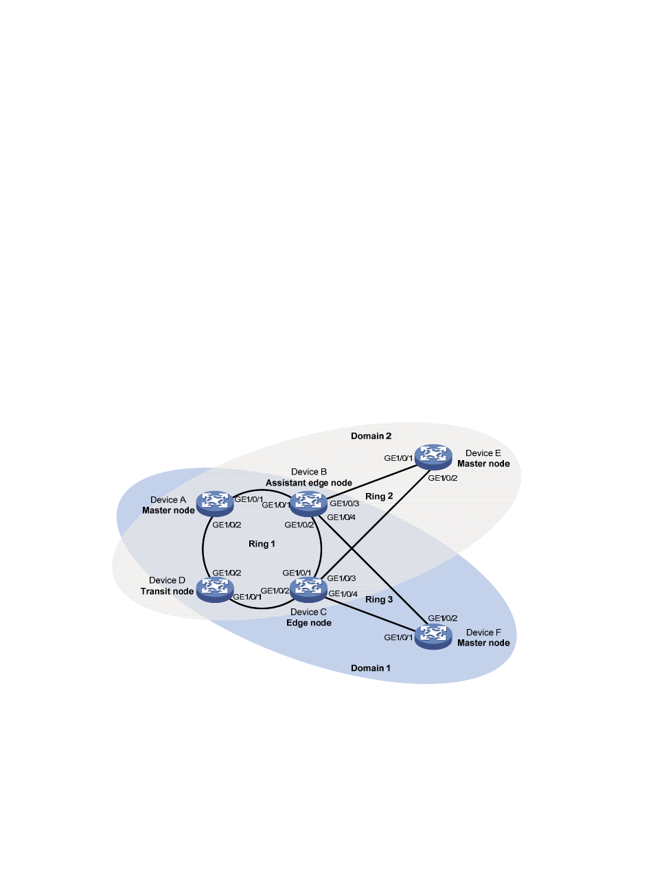
Device A, Device B, Device C, Device D, and Device F form RRPP domain 1, and VLAN 100 is the
primary control VLAN of the RRPP domain. Device A is the master node of the primary ring, Ring 1;
Device D is the transit node of Ring 1; Device F is the master node of the subring Ring 3; Device C
is the edge node of the subring Ring 3; Device B is the assistant-edge node of the subring Ring 3.
•
Device A, Device B, Device C, Device D, and Device E form RRPP domain 2, and VLAN 105 is the
primary control VLAN of the RRPP domain. Device A is the master node of the primary ring, Ring 1;
Device D is the transit node of Ring 1; Device E is the master node of the subring Ring 2; Device C
is the edge node of the subring Ring 2; Device B is the assistant-edge node of the subring Ring 2.
•
Specify VLAN 1 as the protected VLAN of domain 1 and VLAN 2 the protected VLAN of domain
2. You can implement VLAN-based load balancing on Ring 1.
•
Because the edge node and assistant-edge node of Ring 2 are the same as those of Ring 3 and the
two subrings have the same SRPTs, you can add Ring 2 and Ring 3 to the RRPP ring group to reduce
Edge-Hello traffic.
Figure 23 Network diagram for intersecting-ring load balancing configuration
Configuration procedure
1.
Configure Device A.
# Create VLANs 1 and 2, map VLAN 1 to MSTI 1 and VLAN 2 to MSTI 2, and activate MST region
configuration.
<DeviceA> system-view
[DeviceA] vlan 1 to 2