Ipv4-based vrrp configuration examples, Single vrrp group configuration example, Network requirements – H3C Technologies H3C S10500 Series Switches User Manual
Page 149: Configuration procedure
140
IPv4-based VRRP configuration examples
This section provides these configuration examples:
•
Single VRRP group configuration example
•
VRRP interface tracking configuration example
•
VRRP with multiple VLANs configuration example
Single VRRP group configuration example
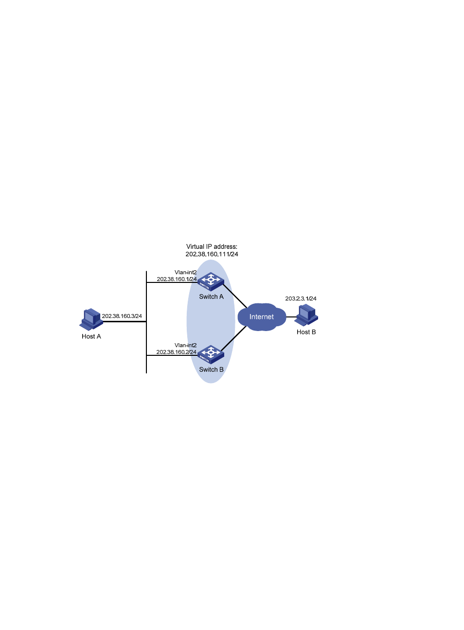
Network requirements
•
Host A wants to access Host B on the Internet, using 202.38.160.111/24 as its default gateway.
•
Switch A and Switch B belong to VRRP group 1 with the virtual IP address of 202.38.160.111/24.
•
When Switch A operates normally, packets sent from Host A to Host B are forwarded by Switch A;
when Switch A fails, packets sent from Host A to Host B are forwarded by Switch B.
Figure 37 Network diagram for single VRRP group configuration
Configuration procedure
1.
Configure Switch A
# Configure VLAN 2.
<SwitchA> system-view
[SwitchA] vlan 2
[SwitchA-vlan2] port gigabitethernet 1/0/5
[SwitchA-vlan2] quit
[SwitchA] interface vlan-interface 2
[SwitchA-Vlan-interface2] ip address 202.38.160.1 255.255.255.0
# Create VRRP group 1 and set its virtual IP address to 202.38.160.111.
[SwitchA-Vlan-interface2] vrrp vrid 1 virtual-ip 202.38.160.111
# Set the priority of Switch A in VRRP group 1 to 110, which is higher than that of Switch B (100), so that
Switch A can become the master.
[SwitchA-Vlan-interface2] vrrp vrid 1 priority 110