Configuration procedure – H3C Technologies H3C S10500 Series Switches User Manual
Page 165
156
•
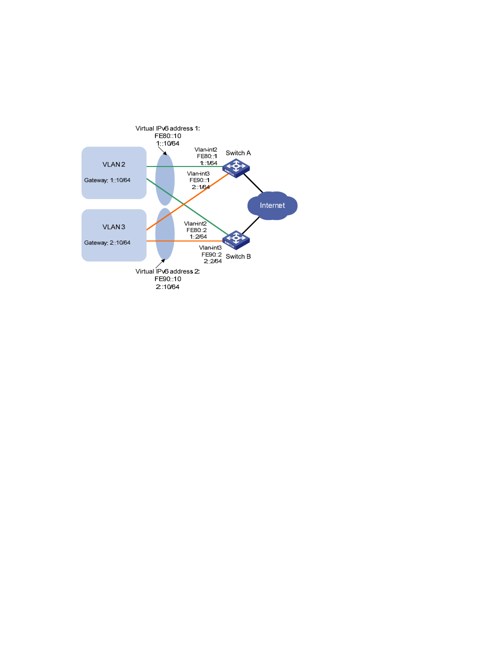
In VRRP group 1, Switch A has a higher priority than Switch B. In VRRP group 2, Switch B has a
higher priority than Switch A. In this case, hosts in VLAN 1 and VLAN can communicate with
external networks through Switch A and Switch B respectively, and when Switch A or Switch B fails,
the hosts can use the other switch to communicate with external networks to avoid communication
interruption.
Figure 42 Network diagram for configuration of multiple VRRP groups in different VLANs
Configuration procedure
1.
Configure Switch A
# Configure VLAN 2.
<SwitchA> system-view
[SwitchA] ipv6
[SwitchA] vlan 2
[SwitchA-vlan2] port gigabitethernet 1/0/5
[SwitchA-vlan2] quit
[SwitchA] interface vlan-interface 2
[SwitchA-Vlan-interface2] ipv6 address fe80::1 link-local
[SwitchA-Vlan-interface2] ipv6 address 1::1 64
# Create VRRP group 1 and set its virtual IPv6 addresses to FE80::10 to 1::10.
[SwitchA-Vlan-interface2] vrrp ipv6 vrid 1 virtual-ip fe80::10 link-local
[SwitchA-Vlan-interface2] vrrp ipv6 vrid 1 virtual-ip 1::10
# Set the priority of Switch A in VRRP group 1 to 110, which is higher than that of Switch B (100), so that
Switch A can become the master in VRRP group 1.
[SwitchA-Vlan-interface2] vrrp ipv6 vrid 1 priority 110
[SwitchA-Vlan-interface2] quit
# Enable Switch A to send RA messages, so that hosts in VLAN 2 can learn the default gateway address.
[SwitchA-Vlan-interface2] undo ipv6 nd ra halt
[SwitchA-Vlan-interface2] quit
# Configure VLAN 3.
[SwitchA] vlan 3