Vrrp with multiple vlans configuration example, Network requirements, Configuration procedure – H3C Technologies H3C S10500 Series Switches User Manual
Page 155
146
Admin Status : Up State : Master
Config Pri : 100 Running Pri : 100
Preempt Mode : Yes Delay Time : 5
Auth Type : Simple Key : hello
Virtual IP : 202.38.160.111
Virtual MAC : 0000-5e00-0101
Master IP : 202.38.160.2
The output shows that when VLAN-interface 3 on Switch A is not available, the priority of Switch A is
reduced to 80 and it becomes the backup. Switch B becomes the master and packets sent from Host A
to Host B are forwarded by Switch B.
VRRP with multiple VLANs configuration example
Network requirements
•
Hosts in VLAN 2 use 202.38.160.100/25 as their default gateway and hosts in VLAN 3 use
202.38.160.200/25 as their default gateway.
•
Switch A and Switch B belong to both VRRP group 1 and VRRP group 2. The virtual IP address of
VRRP group 1 is 202.38.160.100/25, and that of VRRP group 2 is 202.38.160.200/25.
•
In VRRP group 1, Switch A has a higher priority than Switch B. In VRRP group 2, Switch B has a
higher priority than Switch A. In this case, hosts in VLAN 2 and VLAN 3 can communicate with
external networks through Switch A and Switch B respectively, and when Switch A or Switch B fails,
the hosts can use the other switch to communicate with external networks to avoid communication
interruption.
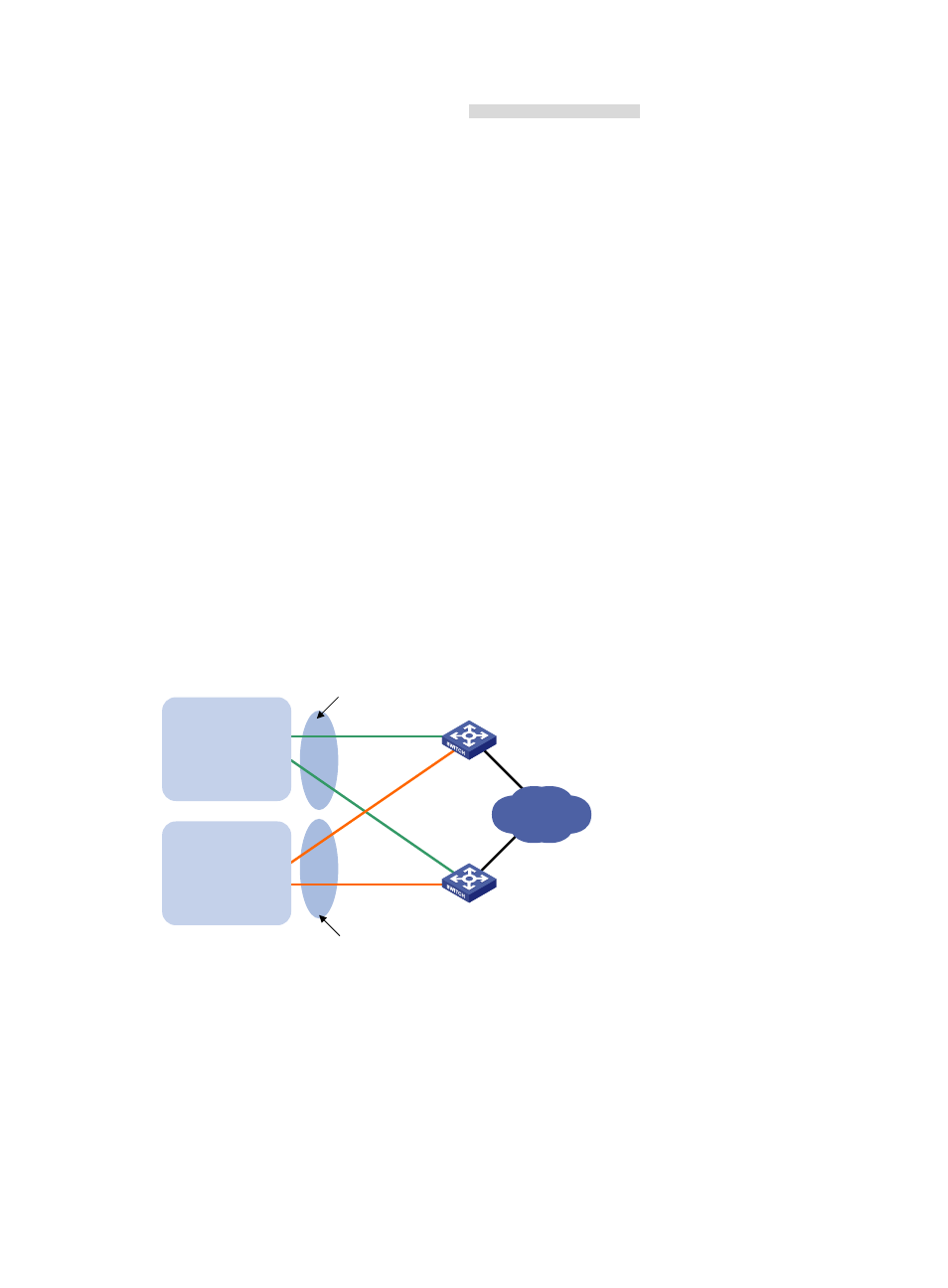
Figure 39 Network diagram for configuration of multiple VRRP groups in different VLANs
Switch A
Switch B
Virtual IP address 1:
202.38.160.100/25
Virtual IP address 2:
202.38.160.200/25
Vlan-int2
202.38.160.1/25
Vlan-int2
202.38.160.2/25
Internet
VLAN 2
Gateway:
202.38.160.100/25
VLAN 3
Gateway:
202.38.160.200/25
Vlan-int3
202.38.160.130/25
Vlan-int3
202.38.160.131/25
Configuration procedure
1.
Configure Switch A
# Configure VLAN 2.
<SwitchA> system-view
[SwitchA] vlan 2
[SwitchA-vlan2] port gigabitethernet 1/0/5
[SwitchA-vlan2] quit