Yaskawa Varispeed-686SS5 CIMR-SSA User Manual
Page 29
30
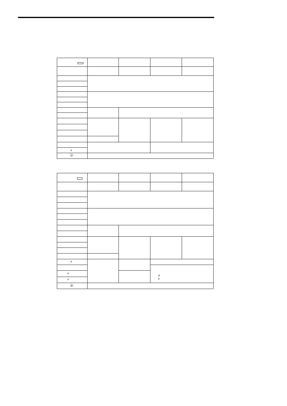
(4) Functions of Main Circuit Terminals
The following table outlines the functions of the main circuit terminals. Wire according to each
terminal function.
Table 3
200V Class Terminal Functions
Models
CIMR-SSA
20P4 to 27P5
2011 to 2015
2018 to 2022
2030 to 2075
Max Applicable
M
O
0 4 to 7 5 kW
11 to 15 kW
18 5 to 22 kW
30 to 75 kW
Max Applicable
Motor Output
0.4 to 7.5 kW
11 to 15 kW
18.5 to 22 kW
30 to 75 kW
R (L1)
S (L2)
Main circuit input power supply
T (L3)
p p
pp y
U (T1)
V (T2)
Inverter output
W (T3)
p
B1
Braking resistor unit
B2
Braking resistor unit
©
• DC reactor
(¨1 ¨2)
• DC reactor
• DC bus terminals
(¨1 ©)
• Braking unit
(¨3 ©)
¨
1
C
(¨1 - ¨2)
• DC bus terminals
C
(¨ 1 - ¨ 2)
• DC bus terminals
C u
(¨1 - ©)
• Braking unit
g
(¨3 - ©)
(¨1 and ¨2
i l
¨
2
DC bus terminals
(¨1 - ©)
DC bus terminals
(¨ 1 - © )
• Braking unit
Braking unit
(¨3 - ©)
(¨1 and ¨2
terminals not
provided) *
¨
3
• Braking unit
(¨3 - ©)
provided)
r
Cooling fan power supply
Cooling fan power supply
Ground terminal (Ground resistance : 100Ω or less)
Table 4
400V Class Terminal Functions
Models
CIMR-SSA
40P4 to 4015
4018 to 4045
4055 to 4160
4220 to 4300
Max Applicable
M
O
0 4 to 15 kW
18 5 to 45 kW
55 to 160 kW
185 to 300 kW
Max Applicable
Motor Output
0.4 to 15 kW
18.5 to 45 kW
55 to 160 kW
185 to 300 kW
R (L1)
S (L2)
Main circuit input power supply
T (L3)
U (T1)
V (T2)
Inverter output
W (T3)
B1
Braking resistor unit
B2
Braking resistor unit
©
• DC reactor
(¨1 ¨2)
• DC bus terminals
• Braking unit
• DC bus terminals
(¨1 ©)
¨
1
C
(¨1 - ¨2)
• DC bus terminals
• DC bus terminals
(¨1 - ©)
Braking unit
(¨3 - © )
(¨1 and ¨2
(¨1 - ©)
• Braking unit
¨
2
• DC bus terminals
(¨1 - ©)
(¨1 ©)
• Braking unit
(¨3 - ©)
(¨1 and ¨2
terminals not
id d)
*
Braking unit
(¨3 - © )
(¨2 terminal not
¨
3
(¨3 - ©)
provided)
*
(¨2 terminal not
provided)
Cooling fan power
r
Cooling fan power
supply
• Cooling fan power supply
200
Cooling fan power supply
(Control power supply)
r - 200 : 200 to 230 VAC input
400
r - 200 : 200 to 230 VAC input
r - 400 : 380 to 460 VAC input
Ground terminal (Ground resistance : 10Ω or less)
*
The models of 200V 30 to 75kW or 400V 55 to 160kW cannot be connected with DC power
supply. Terminal ¨3 is for exclusive use for connecting a braking unit. Do not connect DC
power supply to terminal ¨3.