Yaskawa Varispeed-686SS5 CIMR-SSA User Manual
Page 68
7
TROUBLESHOOTING
69
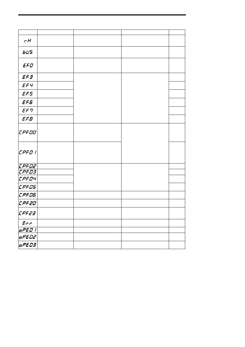
Table 31
Fault Diagnosis and Corrective Actions (Cont’d)
Fault Display
Description
Details
Corrective Action
Rank*
Braking resistor unit overheat
(RH)
The braking resistor unit temperature has
exceeded the allowable value.
(Protects only inverter built-in type)
Reduce the regenerative load.
A
Transmission fault with trans-
mission option (bUS)
Transmission fault with transmission op-
tion (detectedwhen thefault contirnuedfor
2.5 seconds)
Check the transmission devices and the
transmission signals.
A
External fault from transmis-
sion option (EF0)
External fault was input from the transmis-
sion option.
External fault, defined by user specifica-
tion, was input from the transmission op-
tion. Find the external fault items from the
I/O list and correct it.
B
External fault at terminal 3
(EF3)
B
External fault at terminal 4
(EF4)
B
External fault at terminal 5
(EF5)
Fault occurred in the external control
circuit.
Check the condition of the input terminal.
If the fault is displayed when terminal is
B
External fault at terminal 6
(EF6)
circuit.
The inverter operates according to the set-
tings of constants H1-01 to H1-06.
If the fault is displayed when terminal is
not connected, replace the inverter.
B
External fault at terminal 7
(EF7)
B
External fault at terminal 8
(EF8)
B
Control circuit fault 1 (CPF00)
(Digital operator transmission
fault)
• Transmission between the inverter and
digital operator cannot be established 5
seconds after supplying power.
• MPU peripheral element check fault
(initial)
• Insert the digital operator connector
again
A
Control circuit fault 2 (CPF01)
(Digital operator transmission
fault)
• Transmission between the inverter and
digital operator is established once after
supplying power, but later transmission
fault continues for more than 2 seconds.
• MPU peripheral element check fault
(initial)
again.
• Check the control circuit wiring.
• Replace the control card.
A
Baseblock circuit fault (CPF02)
A
EEPROM fault (CPF03)
A
CPU internal A/D converter
fault (CPF04)
Inverter control unit fault.
Replace the control card.
A
CPU external A/D converter
fault (CPF05)
A
Option card connection fault
(CPF06)
The option card is not installed correctly. Install the option card again.
A
A/D converter fault in option
card (CPF20)
Option card (AI-14B/U) A/D converter
fault
• Check the option card contact part.
• Replace the option card.
A
Cross-diagnose fault between
transmission option and control
card (CPF23)
Diagnosis data has not been updated for
more than 0.2 seconds between the trans-
mission option and the control card.
• Check the transmission option contact
part.
• Replace the transmission option.
A
EEPROM writing fault (Err)
EEPROM internal data did not match
when initializing the constant.
Replace the control card.
A
kVA selection fault (OPE01)
kVA selection fault
Check and set the constant data.
D
Constant setting range fault
(OPE02)
Constant data is out of range.
Check the constant data settings.
D
Multi-function contact input
selection fault (OPE03)
The same values are set except for F and
FF.
Check the function selection.
D
(Cont’d)