5 setting operation conditions, 1 digital operator key description, 5setting operation conditions – Yaskawa Varispeed-686SS5 CIMR-SSA User Manual
Page 55
56
5
SETTING OPERATION CONDITIONS
5.1
DIGITAL OPERATOR KEY DESCRIPTION
FWD/REV: Selects forward or reverse run alternately.
JOG: Jog run is possible while JOG key is held pressed.
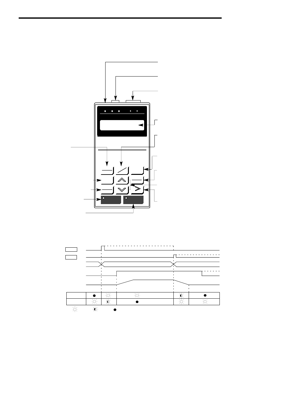
LOCAL
REMOTE
DIGITAL OPERATOR
JVOP-132
DSPL
DATA
ENTER
FWD
REV
RESET
RUN
STOP
DRIVE FWD
REV
REMOTE
SEQ
DRIVE
PRGM
Mode Indicator LEDs
(All LEDs blink if a fault occurs in the drive mode.)
Display
JOG
DRIVE FWD REV
REMOTE
REF
SEQ
Drive Mode Display
Lights when the drive mode is selected.
OFF when the program mode is selected.
Rotating Direction Display
FWD
:
Lights at forward run.
REV
:
Lights at reverse run.
Remote Mode Display
SEQ
:
Lights when the remote mode is selected
for the run command.
REF : Lights when the remote mode is selected
for the frequency reference.
Displays set values of each function or monitoring
values such as speed and output current. (5 char-
acters)
Lights in operation mode using the signals input
from the control circuit terminals or option cards.
Mode Selection Key
Selects the drive mode and the program mode
alternately. (Mode selection is possible even
during operation.) When the drive mode is se-
lected, DRIVE LED lights.
Operation Mode Selection Key
Selects the REMOTE and LOCAL (digital operator)
mode alternately.
RUN: Red LED lights when RUN is depressed.
(Refer to Fig. 27.)
STOP: Red LED lights when STOP is depressed.
(Refer to Fig. 27.)
Digit Selection Key
Selects the digit of a set value to be changed.
The selected digit blinks. (This key also
used as the reset key if a fault is displayed.)
Numeral Change Key
Changes set values or constant numbers.
: Increment key
: Decrement key
Read/Write Key
Displays the set values of the constants. Depress-
ing this key again after setting a value enters it.
Display Selection Key
Selects the data to be displayed in predetermined
sequence. (Display sequence is shown in Table 21.)
Operation Command Keys
Used to operate the inverter by the digital operator.
They are valid only in the drive mode.
<
>
Fig.
26
Digital Operator Key Description
RUNandSTOP LEDs light, blink, andgoOFF dependingon thestatus ofoperation.
RUN
STOP
Key
RUN
Internal Run
Command
Speed
Reference
Motor
Reference
STOP
STOP
RUN LED
STOP LED
*
:
ON
: Blink
: OFF
* LED goes OFF at flux vector control.
Key
Fig.
27
Run and Stop LED Display