To test continuity, To test continuity -21 – RIGOL M300 User Manual
Page 31
RIGOL
© 2007 RIGOL Technologies, Inc.
User’s Guide for DM3000 Series
1-21
To Test Continuity
The following shows the system connections and the selection of measurement
functions. The practice provides a guide to get familiar with the Continuity
measurement technique.
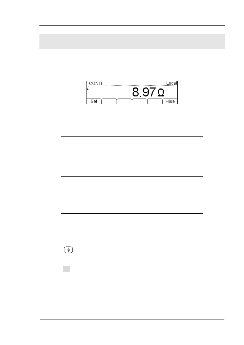
Figure 1- 27 Continuity Measurement Data Interface
Table1- 8 Continuity Measurement Characteristics
Tests Current
1mA
Max Resolution
Range fixed at 2KΩ
Open-circuit Voltage <7V
Input Protection
1000V (HI
Terminal)
Configurable
Parameters
0≤R
testing
≤Short-circuit impedance
(0Ω≤Short-circuit impedance≤2kΩ)
Steps:
1. Connect test leads as Figure 1- 28 shown. Red test lead connects the HI
Terminal, Black test lead connects the LO Terminal.
2. Press
to select the Continuity Measurement.
3. Setup the Short-circuit resistance.
Press Set button to set up the Short-circuit Impedance.
The default value is 10Ω. User may carry on the Continuity measurement
directly without modification.
4. Lead test leads into circuit, start to measure.