Top panel/side panel, Panel descriptions – Roland V-60HD Multi-Format HD Video Switcher and UVC-01 USB Video Capture Kit User Manual
Page 7
7
Panel Descriptions
Top Panel/Side Panel
NO.
Name
Explanation
Page
6
[MODE] button
This switches the functioning of the AUX/MEMORY buttons.
AUX/MEMORY [1]–[8] buttons
When the [MODE] button is lighted in green
The buttons function as AUX-bus selection buttons. They select the video (channel 1–8) to send to the
AUX bus. The selected button lights up in red.
The respective buttons also function as indicators showing the input status of the video.
When the [MODE] button is lighted in blue
The buttons function as preset-memory selection buttons. These save video and audio settings, the state
of the operation panel, and other current settings, and call up settings saved in memory.
7
Cross-point [1]–[8] buttons
These select the video to output.
PGM/A bus end
These select the video (channel 1–8) to send to the PGM/A bus. The video on the
PGM/A bus becomes the final video output. The selected button lights up in red.
PST/B bus end
These select the video (channel 1–8) to send to the PST/B bus. The video on the
PST/B bus is the preset video (the video to be output next). The selected button
lights up in green.
* While video compositing is in progress, the button lights up in red.
* The system functions as just described when the operation mode is set to “PGM/PST mode.” Operation
differs when in the A/B mode.
8
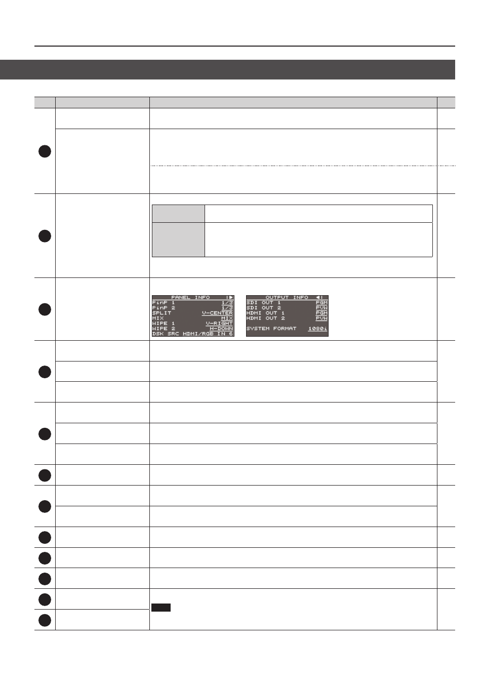
Built-in display
This displays current information about the V-60HD. There are the two types—PANEL INFO and OUTPUT
INFO—and you use the [VALUE] knob to switch between them.
—
9
[MENU] button
This switches between displaying or hiding the menu. The menu appears on the unit’s built-in display
and on the multi-view monitor (p. 10) connected to the MULTI-VIEW connector.
[EXIT] knob
This returns you to the menu one level higher.
[VALUE] knob
Turning: This selects a menu item or changes a setting value.
Pressing: This accepts the selected menu item or applies changes to a setting. It also executes operations.
10
[LEVEL] knob
During DSK compositing, this adjusts the amount of keying (transparency).
[GAIN] knob
During DSK compositing, this adjusts the degree of edge blur (the semi-transmissive region) for keying.
[PVW] button
When this is on (lighted), it makes the DSK compositing results the preview output.
11
[CUT] button
[AUTO] button
These make the preset video (the video to output next) the final output.
12
Video fader
This manually makes the preset video (the video to be output next) the final output.
Transition indicator
The indicator for the final-output bus end lights up.
13
[OUTPUT FADE] button
This performs a fade-in or fade-out for the final output video. This flashes or lights up during a fade or
fade-out.
14
HDCP indicator
This lights up, flashes, or goes dark according to the V-60HD’s “HDCP” setting and the connected status of
HDCP-compatible equipment.
15
[DSK] button
This switches DSK composition on or off. When on, the [DSK] button lights up.
16
Cooling-fan exhaust port
These expel internal heat to keep temperatures inside the V-60HD cool.
NOTE
Never obstruct the cooling-fan intake and exhaust ports. Obstructing the intake and exhaust ports
might result in a temperature rise inside the V-60HD and lead to malfunction due to heat.
—
17
Cooling-fan intake port