Side panel, Panel descriptions – Roland V-8HD HDMI Video Switcher User Manual
Page 3
3
Panel Descriptions
Name
Explanation
8
AUX / PinP SOURCE / MEMORY
[1]–[8] buttons
Select the object of operation according to the
function selected by the [MODE] button.
The selected button lights up.
The respective buttons also function as indicators
showing the input status of the video.
Lit white
Valid video is being input.
Blink white
Video whose format differs from the
system format setting is input.
Unlit
No video is input.
[MODE] button
Explanation
AUX
The buttons function as AUX-bus selection buttons.
They select the video (channel 1–8) to send to the AUX bus.
PinP1 SOURCE
The buttons function as source screen select buttons for
PinP 1.
The buttons select the video (channels 1–8) that is shown
in the inset screen of PinP 1.
PinP2 SOURCE
The buttons function as source screen select buttons for
PinP 2.
The buttons select the video (channels 1–8) that is shown
in the inset screen of PinP 2.
MEMORY
The buttons function as preset-memory selection buttons.
These save video and audio settings, the state of the
operation panel, and other current settings, and call up
settings saved in memory.
Press this button to recall settings; long-press this button
to save settings.
9
SPLIT / VFX A, SPLIT / VFX B
SPLIT/VFX [A] knob
Adjust the depth of the effect when split/visual
effect A is on.
SPLIT/VFX [B] knob
Adjust the depth of the effect when split/visual
effect B is on.
* By holding down the SPLIT/VFX button and turning the SPLIT/VFX knob, you can
change the type of split/visual effect.
SPLIT/VFX [A] button
If this is on (lit), the effect of split/visual effect A is
applied to the video selected by the Cross-point
A [1]–[8] buttons.
SPLIT/VFX [B] button
If this is on (lit), the effect of split/visual effect B is
applied to the video selected by the Cross-point
B [1]–[8] buttons.
* If the SPLIT/VFX type is set to split, it is not possible to turn both A and B on.
10
A/PGM, B/PST
Cross-point A [1]–[8]
buttons
Selects the video to input to bus A of the video
mixer.
The selected button lights up.
When the SPLIT/VFX [A] button is on, the split/
visual effect A effect is applied to the video.
Cross-point B [1]–[8]
buttons
Selects the video to input to bus B of the video
mixer.
The selected button lights up.
* While compositing of the video is in progress
it lit red.
When the SPLIT/VFX [B] button is on, the split/
visual effect B effect is applied to the video.
Name
Explanation
11
[TRANSITION]
button
Selects the video transition effects.
MIX
The two pictures are blended
together as the video is switched.
WIPE
The original video is broken into by
the next video.
12
[CUT] button
[AUTO] button
These make the preset video (the video to output
next) the final output.
[CUT]
The picture switches instantly.
[AUTO]
The picture switches with a transition
effect applied.
13
Video fader
Manually switch between the videos being input
to bus A and B, and send them to the program
output.
Transition indicators
The indicator for the final-output bus end lights
up.
14
Monitor
Shows the input/output video, a still image, or a
menu screen.
15
[MENU] button
Switches between displaying or hiding the menu.
The menu appears on the built-in monitor
and the display connected to the OUTPUT 3
connector.
16
[EXIT] button
Returns you to the menu one level higher.
17
[VALUE] knob
Turning
Selects a menu item or changes a
setting value.
Pressing
Accepts the selected menu item or
applies changes to a setting. It also
executes operations.
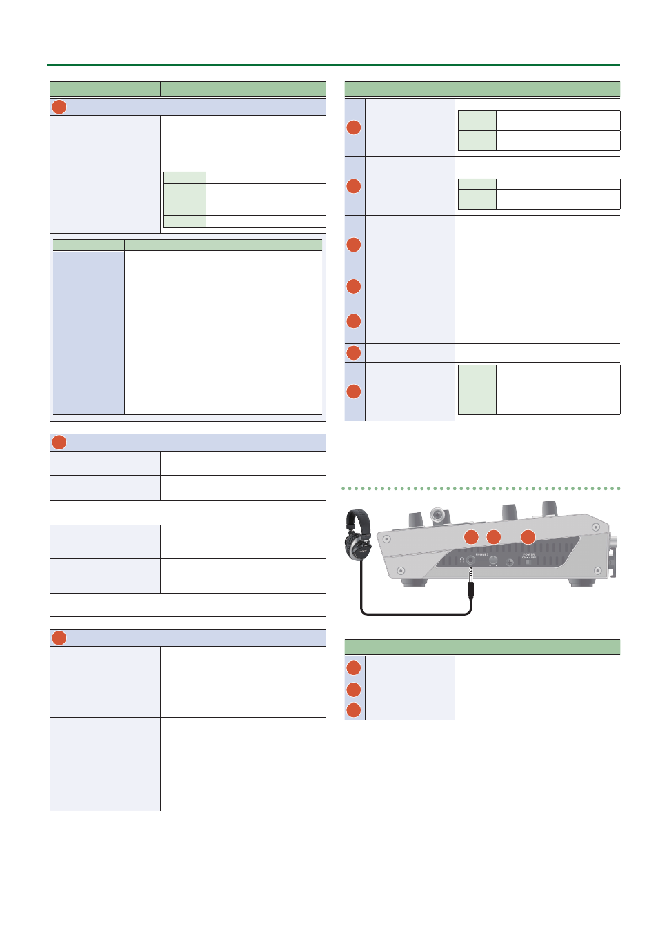
Side panel
20
18
19
Name
Explanation
18
PHONES jack
(Stereo miniature type)
Connect headphones here.
19
[PHONES] knob
Adjusts the volume of the headphones.
20
[POWER] switch
Turns the power on/off.