T load adapter, Assembly, 3 t load adapter – d&b T-Series User Manual
Page 10
2.3.
T Load adapter
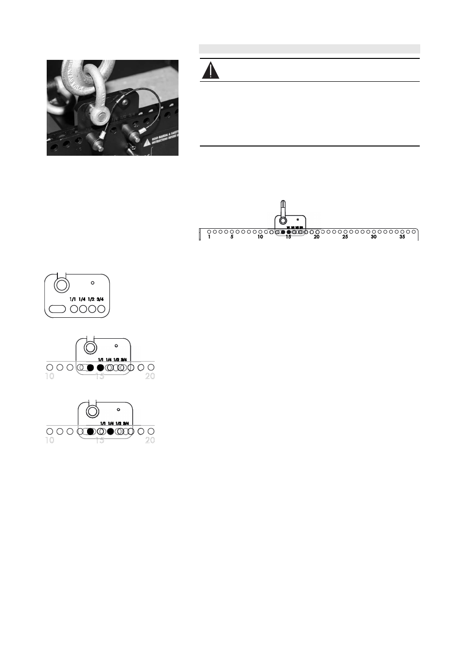
Fig. 6: T Load adapter
WARNING!
- Before attaching the Load adapter check the 1 t shackle is
properly fitted to the Load adapter and secured against
loosening.
- Ensure the Load adapter is properly attached to the center
bar of the frame and both Locking pins are fully inserted
and locked securely before lifting the array.
The Load adapter is attached to the center bar of the Flying frame
and fixed using its two Locking pins 6 mm.
In conjunction with the hole index of the center bar the Load adapter
provides a 1/4-hole resolution.
Fig. 7: T Flying frame hole index
Assembly
The Load adapter is equipped with four holes and one elongated hole.
The elongated hole always refers to the calculated main hole of the hole
index.
To attach the Load adapter proceed as follows:
15
15
20
20
10
Fig. 8: Hole 14 (1/1)
15
15
20
20
10
Fig. 9: Hole 14 + 1/4
Example:
Hole 14 has been calculated using ArrayCalc.
1.
Attach the Load adapter to the center bar of the frame with the
elongated hole aligned to hole 14 of the hole index.
2.
Insert and lock the first Locking pin to hole 14.
3.
Move the Load adapter as long as the hole marked with 1/1 is in
line with the next hole of the hole index.
4.
Insert and lock the second Locking pin.
To achieve other hole values (e.g. 14 + 1/4) align the Load adapter to
the desired hole value (1/4, 1/2 or 3/4 detents) and insert the second
Locking pin.
T-Series Rigging manual
(1.1 EN)
Page 10 of 44