T-series locking pins, Assembly – d&b T-Series User Manual
Page 9
2.2.
T-Series Locking pins
WARNING!
The steel wires between the locking pins and the cabinets and
rigging components are not intended to carry any load.
The cabinet's weight must only be carried by the Front and
Splay/Rear links in conjunction with the front and rear rigging
strands of the loudspeaker cabinets and the Flying frame.
- Ensure all Locking pins are fully inserted and securely locked
before lifting any load.
B
B
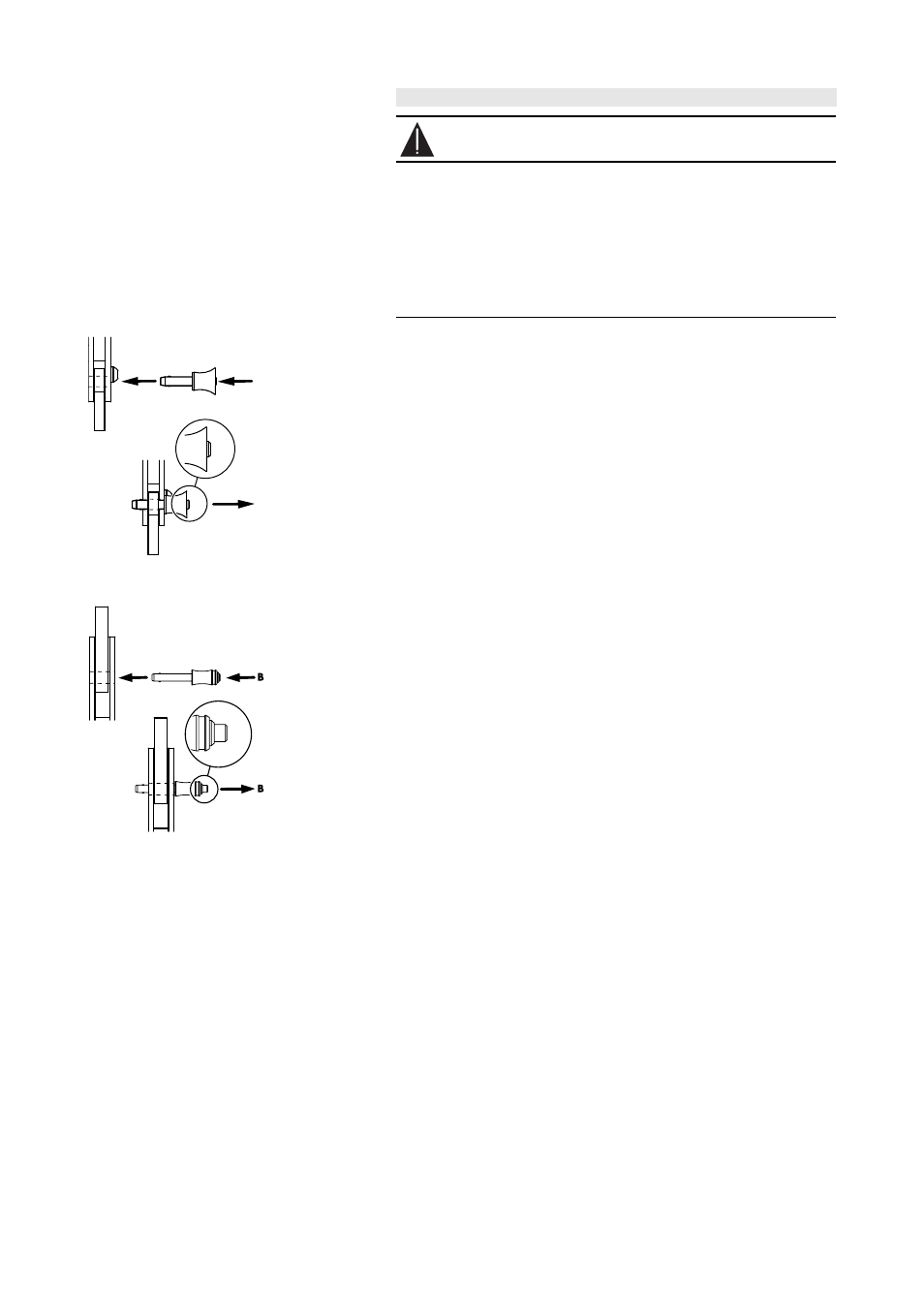
Fig. 4: Locking pins
for the cabinet's Front links.
Fig. 5: Locking pins
for the cabinet's Splay/Rear links
the Flying frame and the Load adapters.
The T-Series cabinets are equipped with the following Locking pins:
- Two Locking pins 5 mm for the cabinet Front links.
- Two (T10) resp. three (T-SUB) Locking pins 6 mm for the Splay/Rear
link on the central rear rigging strand.
The T Flying frame is equipped with the following Locking pins:
- Two Locking pins 6 mm [5.1] on the center bar of the frame to
connect the Splay/Rear link of the first cabinet to the frame.
- One Locking pin 5 mm [5.2] on either side at the front of the frame
to connect the Front links of the first cabinet to the frame.
- The two Load adapters supplied with the Flying frame are equipped
with a pair of Locking pins 6 mm.
Assembly
The quick lock mechanism applies to all types of Locking pins listed
above. To attach the Locking pin proceed as follows:
1.
Press the button
[B] to release the locking mechanism.
2.
Insert the Locking pin through the respective link or socket until it is
fixed in place.
3.
Release the button to lock the pin.
4.
Recheck the Locking pin is securely locked by briefly pulling the
Locking pin towards you.
To release and remove the Locking pins follow the steps 1 to 3 in
reversed order.
T-Series Rigging manual
(1.1 EN)
Page 9 of 44