Rig the cabling, Check the assembly – d&b T-Series User Manual
Page 29
- On the rear of the assembly preset the desired splay angle at the
rear rigging strand of the bottom cabinet of the upper assembly.
- Raise the bottom assembly and hook the Splay link over the preset
Locking pin.
- Slightly lower the bottom assembly to enable the second Locking pin
(safety pin) to be inserted.
- Insert the second Locking pin to secure the Splay link of the cabinet.
- To add further assemblies proceed in the same manner until the
array is completed.
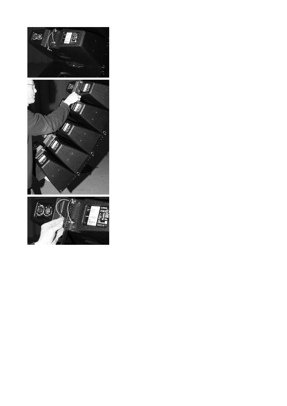
5. Rig the cabling
- Connect the flying cables and link cables according to the number of
amplifier channels and cabinets used.
- Attach the cable pick depending on the chosen type of suspension
(Single or Dual pickpoint operation setup) as described in section 3.3
Suspension of the Flying frame on page 15.
6. Check the assembly
- Before hoisting the array to its operating position recheck the actual
status of the assembly according to the checklist given in section 5.
Checklist for the assembly of T-Series arrays on page 38.
T-Series Rigging manual
(1.1 EN)
Page 29 of 44