T-sub column, Limitation, Preparations – d&b T-Series User Manual
Page 23: Order of assembly, Suspend the flying frame, Prepare the first t-sub cabinet, Attach the flying frame to the first t-sub cabinet
4.1.2. T-SUB Column
Limitation
A maximum of 10 x T-SUB cabinets are allowed to be flown as a SUB
column.
Preparations
Prepare the flying cables and link cables according to the number of
amplifier channels and cabinets used.
Order of assembly
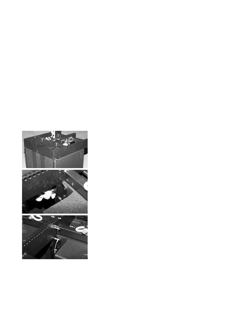
1. Suspend the Flying frame
- Suspend the Flying frame according to the chosen type of suspension
as described in section 3.3 on page 15.
- Release the two Locking pins at the front of the frame.
2. Prepare the first T-SUB cabinet
- Prepare the Front links of the first T-SUB cabinet as described in
3. Attach the Flying frame to the first T-SUB cabinet
- Lower the frame onto the cabinet until the Front links fit into the slots
at the front of the frame.
- Insert and lock the frame's Locking pins on both sides.
- Release the two Locking pins at the support point for the Rear link on
the track of the frame's center bar.
- Release the Locking pin of the Rear link of the T-SUB cabinet.
- Slide out the Rear link up to its stop position into the track of the
frame's center bar.
- Insert the Locking pin of the Rear link at the T-SUB cabinet.
- Insert the two Locking pins at the support point for the Rear link on
the track of the frame's center bar.
T-Series Rigging manual
(1.1 EN)
Page 23 of 44