2 flash layout, 3 i/o address mapping, Table 5-3 – Artesyn PrAMC-7311 Installation and Use (June 2014) User Manual
Page 53: I/o address mapping, Figure 5-2, Flash layout
Address Mapping
PrAMC-7311 Installation and Use (6806800P34D)
53
5.2.2
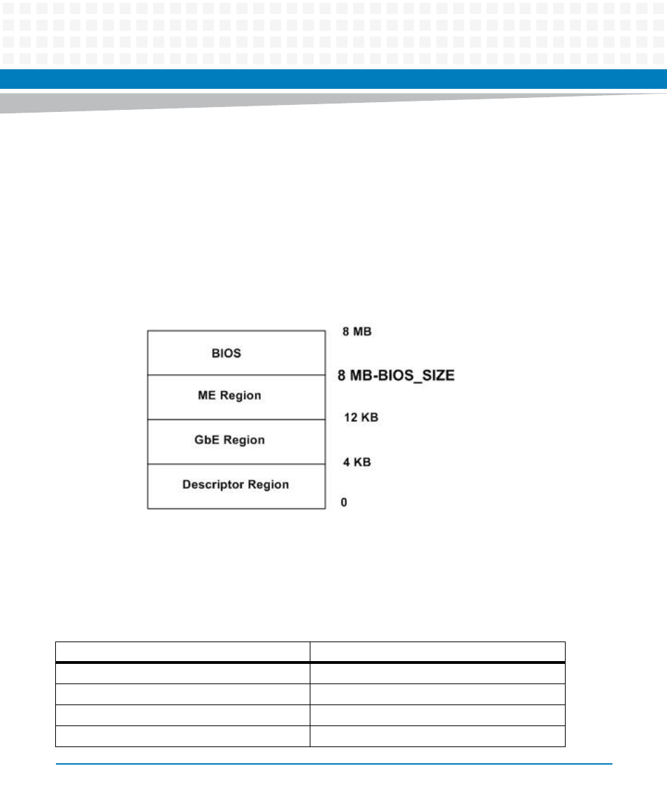
Flash Layout
BIOS can be supported from either firmware hub (LPC) or on SPI, for PrAMC-7311 it is designed
to support from SPI flash and as usually the ME and GbE technology supported firmware also
reside on flash devices only so that total firmware's can be combined into single image and
going to be placed into the SPI flash. PrAMC-7311 support of two flash devices with 8MB each
and with the help of MMC the particular flash can be selected for boot the BIOS, by default
system boot from flash device 0 because default selection line enabled on SPI is of #CS0. Below
the figure is the flash composition to support the BIOS, GbE, ME technologies.
5.3
I/O Address Mapping
The I/O address ranges of all onboard functional units are shown in the next table.
Figure 5-2
Flash Layout
Table 5-3 I/O Address Mapping
Address Range
Device
0x000 - 0x01F
DMA Controller
0x020 - 0x02D
Interrupt controller
0x030 - 0x03D
Interrupt Controller
0x040 - 0x043
Timer