6 led signals, Led signals, Table 19: dc sync/latch and mii management pins – BECKHOFF ET1200 User Manual
Page 26: Table 20: led pins
Pin Description
III-16
Slave Controller
– ET1200 Hardware Description
3.5
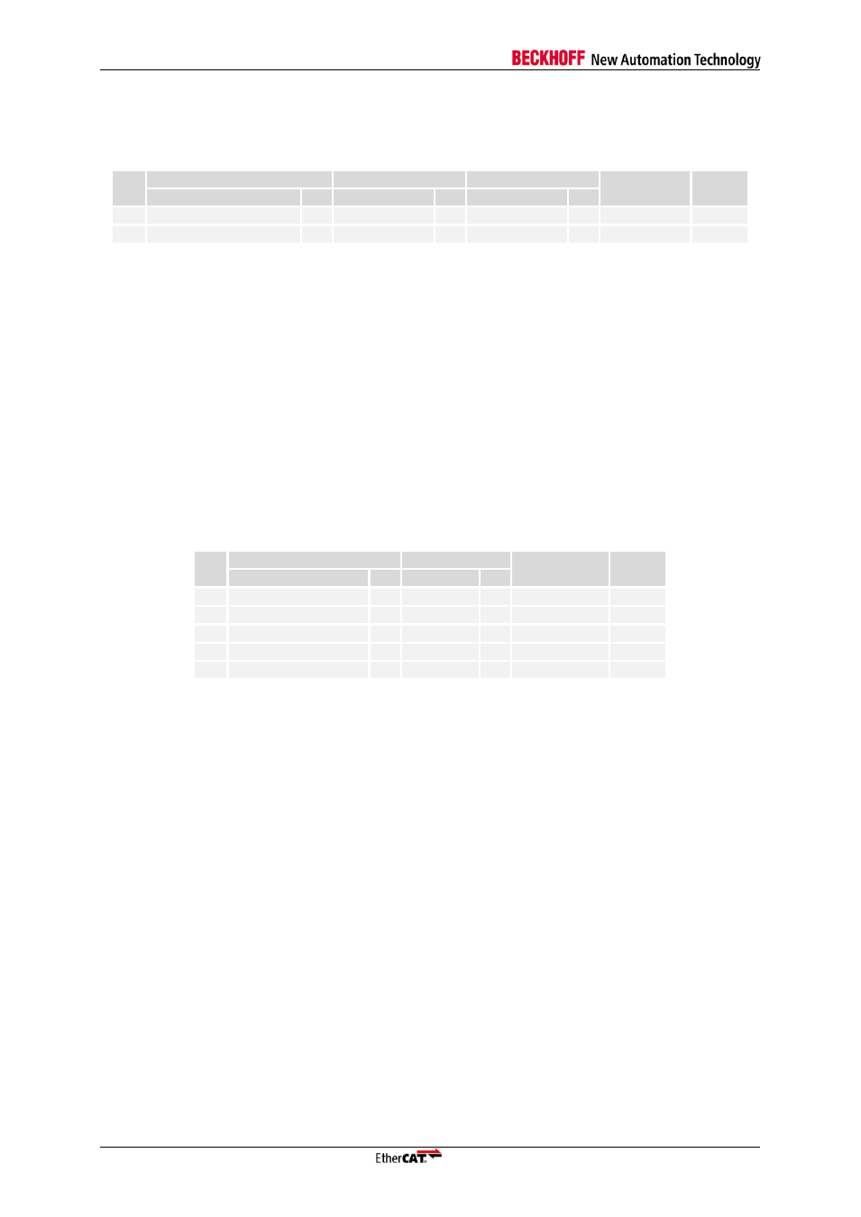
Distributed Clocks SYNC/LATCH Pins, MII Management Data
Table 19: DC SYNC/LATCH and MII Management pins
Pin
Pin
No MII port used
MII port used
Configuration
Internal
PU/PD
Name
Dir
Signal
Dir
Signal
Dir
47
SYNC/LATCH[0]
BD
SYNC/LATCH[0]
I/O
SYNC/LATCH[0]
I/O
48
SYNC/LATCH[1]/MI_DATA
BD
SYNC/LATCH[1]
I/O
MI_DATA
BD
SYNC/LATCH[x]/MI_DATA
SYNC/LATCH[x] are Distributed Clocks SyncSignal output or LatchSignal input, depending on SII
EEPROM configuration. If an MII port is used, SYNC/LATCH[1]/MI_DATA becomes MI_DATA, which
is the Ethernet PHY management interface data signal. SYNC/LATCH signals are not driven (high
impedance) until the EEPROM is loaded (MI_DATA is independent of the EEPROM loaded state).
NOTE: MI_DATA must have a pull-up resistor (4.7k
Ω recommended for ESCs).
3.6
LED Signals
All LED signals are also used as configuration signals. The polarity of each LED signal depends on
the configuration: LED is active high if pin is pulled down for configuration, and active low if pin is
pulled up. Refer to the example schematics for LED connection details.
Table 20: LED pins
Pin
Pin
Signal
Configuration
Internal
PU/PD
Name
Dir
Name
Dir
18
RUN/EEPROM_SIZE
BD
RUN
O
EEPROM_SIZE
WPD
16
LINKACT(0)/MODE[0]
BD
LINKACT(0)
O
MODE[0]
WPD
12
PERR(0)/CLK_MODE[0]
BD
PERR(0)
O
CLK_MODE[0]
WPD
17
LINKACT(1)/MODE[1]
BD
LINKACT(1)
O
MODE[1]
WPD
13
PERR(1)/CLK_MODE[1]
BD
PERR(1)
O
CLK_MODE[1]
WPD
RUN/EEPROM_SIZE
SII EEPROM_SIZE configuration (either 1 Kbit-16 Kbit or 32 Kbit-4 Mbit) sampled at the beginning of
the EEPROM access. Otherwise RUN LED signal, usually. RUN is active high if pin is pulled down,
and active low if pin is pulled up. Refer to example schematics for connection details. RUN LED
should be green.
LINKACT(x)/MODE(x)
Chip MODE configuration pin at power-on, Link/Activity LED output (off=no link, on=link without
activity, blinking=link and activity) for logical port x afterwards. LINKACT(x) is active high if pin is pulled
down, and active low if pin is pulled up. Refer to example schematics for connection details.
Link/Activity LED should be green.
PERR(x)/CLK_MODE(x)
CPU_CLK Mode configuration pin at power-on, Error LED output for logical port x afterwards.
PERR(x) is active high if pin is pulled down, and active low if pin is pulled up. Refer to example
schematics for connection details.
NOTE: PERR(x) LEDs are not part of the EtherCAT indicator specification. They are only intended for testing and
debugging. The PERR(x) LED flashes once if a physical layer receive error occurs. Do not confuse PERR(x)
LEDs with application layer ERR LED, this is not supported by the ESCs and has to be controlled by a
µController.