5 bidirectional mode, 6 output driver, 7 syncmanager watchdog – BECKHOFF ET1200 User Manual
Page 42: Bidirectional mode, Output driver, Syncmanager watchdog, Ω recommended)
PDI Description
III-32
Slave Controller
– ET1200 Hardware Description
6.2.5
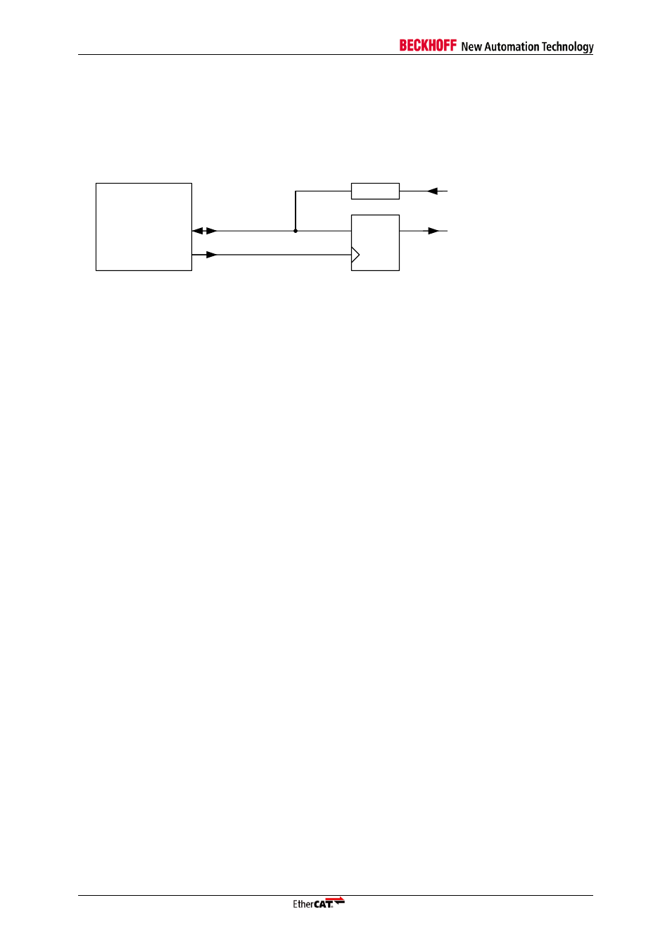
Bidirectional mode
In bidirectional mode, all DATA signals are bidirectional (individual input/output configuration is
ignored). Input signals are connected to the ESC via series resistors, output signals are driven actively
by the ESC. Output signals are permanently available if they are latched with OUTVALID (Flip-Flop or
Latch).
EtherCAT
device
Digital Input
Digital Output
DATA
R
OUTVALID
C1
1D
Q
D-FF
Figure 9: Bidirectional mode: Input/Output connection (R=4.7 k
Ω recommended)
Input sample event and output update event can be configured as described in the Digital
Inputs/Digital Outputs chapter.
An output event is signaled by a pulse on OUTVALID even if the digital outputs remain unchanged.
Overlapping input and output events will lead to corrupt input data.
6.2.6
Output Driver
The output drivers for the digital I/O signals of the ET1200 are active while the SyncManager
watchdog is active (triggered) or disabled, otherwise the output driver is disabled (high impedance).
6.2.7
SyncManager Watchdog
The SyncManager watchdog (registers 0x0440:0x0441) must be either active (triggered) or disabled
for output values to appear on the I/O signals. The SyncManager Watchdog is triggered by an
EtherCAT write access to the output data registers.
If the output data bytes are written independently, a SyncManager with a length of 1 byte is used for
each byte of 0x0F00:0x0F03 containing output bits (SyncManager N configuration: buffered mode,
EtherCAT write/PDI read, and Watchdog Trigger enabled: 0x44 in register 0x0804+N*8). Alternatively,
if all output data bits are written together in one EtherCAT command, one SyncManager with a length
of 1 byte is sufficient (SyncManager N configuration: buffered mode, EtherCAT write/PDI read, and
Watchdog Trigger enabled: 0x44 in register 0x0804+N*8). The start address of the SyncManager
should be one of the 0x0F00:0x0F03 bytes containing output bits, e.g., the last byte containing output
bits.
The SyncManager Watchdog can also be disabled by writing 0 into registers 0x0440:0x0441.
The Watchdog Mode configuration bit is used to configure if the expiration of the SyncManager
Watchdog will have an immediate effect on the I/O signals (output reset immediately after watchdog
timeout) or if the effect is delayed until the next output event (output reset with next output event). The
latter case is especially relevant for Distributed Clock SYNC output events, because any output
change will occur at the configured SYNC event.
Immediate output reset after watchdog timeout is not available if OUTVALID mode set to watchdog
trigger (0x0150[1]=1).
For external watchdog implementations, the WD_TRIG (watchdog trigger) signal can be used. A
WD_TRIG pulse is generated if the SyncManager Watchdog is triggered. In this case, the internal
SyncManager Watchdog should be disabled. For devices without the WD_TRIG signal, OUTVALID
can be configured to reflect WD_TRIG.