4 digital outputs, Digital outputs, Figure 8: digital output principle schematic – BECKHOFF ET1200 User Manual
Page 41
PDI Description
Slave Controller
– ET1200 Hardware Description
III-31
6.2.4
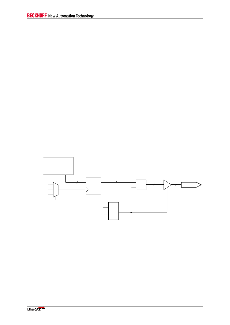
Digital Outputs
Digital Output values have to be written to register 0x0F00:0x0F03 (register 0x0F00 controls I/O[7:0]
etc.). Digital Output values are not read by the Digital I/O PDI using standard read commands,
instead, there is a direct connection for faster response times.
The process data watchdog (register 0x0440) has to be either active or disabled; otherwise digital
outputs will not be updated. Digital outputs can be configured to be updated in four ways:
Digital Outputs are updated at the end of each EtherCAT frame (EOF mode).
Digital outputs are updated with Distributed Clocks SYNC0 events (DC SYNC0 mode).
Digital outputs are updated with Distributed Clocks SYNC1 events (DC SYNC1 mode).
Digital Outputs are updated at the end of an EtherCAT frame which triggered the Process Data
Watchdog (with typical SyncManager configuration: a frame containing a write access to at least
one of the registers 0x0F00:0x0F03). Digital Outputs are only updated if the EtherCAT frame was
correct (WD_TRIG mode).
For Distributed Clock SYNC output, SYNC generation must be activated (register 0x0981). SYNC
output is not necessary (register 0x0151). SYNC pulse length (registers 0x0982:0x0983) should not be
set to 0, because acknowledging of SYNC events is not possible with Digital I/O PDI. Output time is
the beginning of the SYNC event.
An output event is always signaled by a pulse on OUTVALID even if the digital outputs remain
unchanged.
For output data to be visible on the I/O signals, the following conditions have to be met:
SyncManager watchdog must be either active (triggered) or disabled.
Output values have to be written to the registers 0x0F00:0x0F03 within a valid EtherCAT frame.
The configured output update event must have occurred.
16
Output register
Digital I/O output
data register
0x0F00:0x0F01
Digital output pins
16
16
16
EOF
DC Sync0
DC Sync1
D
Q
&
Output event
configuration
Watchdog
&
Output event occured
since watchdog active
Figure 8: Digital Output Principle Schematic
NOTE: The Digital Outputs are not driven (high impedance) until the EEPROM is loaded. The Digital Outputs are
also not driven if the Watchdog is expired. This behavior has to be taken into account when using digital output
signals.