3 spi slave interface, 1 interface, 2 configuration – BECKHOFF ET1200 User Manual
Page 45: 3 spi access, Spi slave interface, Interface, Configuration, Spi access, Table 38: spi signals, Figure 14: spi master and slave interconnection
PDI Description
Slave Controller
– ET1200 Hardware Description
III-35
6.3
SPI Slave Interface
6.3.1
Interface
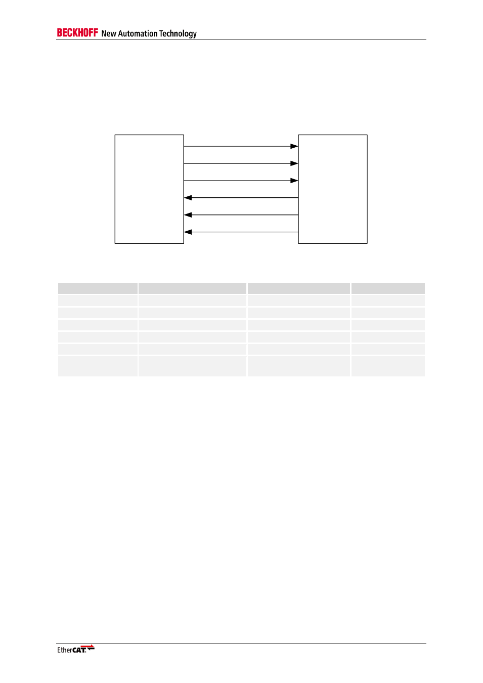
An EtherCAT device with PDI type 0x05 is an SPI slave. The SPI has 5 signals: SPI_CLK, SPI_DI
(MOSI), SPI_DO (MISO), SPI_SEL and SPI_IRQ:
SPI master
(µController)
SPI_SEL
SPI_CLK
SPI_DI
SPI_DO
SPI_IRQ
SPI slave
(EtherCAT
device)
EEPROM_LOADED
Figure 14: SPI master and slave interconnection
Table 38: SPI signals
Signal
Direction
Description
Signal polarity
SPI_SEL
IN
(master → slave)
SPI chip select
Typical: act. low
SPI_CLK
IN
(master → slave)
SPI clock
SPI_DI
IN
(master → slave)
SPI data MOSI
act. high
SPI_DO
OUT
(slave → master)
SPI data MISO
act. high
SPI_IRQ
OUT
(slave → master)
SPI interrupt
Typical: act. low
EEPROM_LOADE
D
OUT
(slave → master)
PDI is active, EEPROM is
loaded
act. high
6.3.2
Configuration
The SPI slave interface is selected with PDI type 0x05 in the PDI control register 0x0140. It supports
different timing modes and configurable signal polarity for SPI_SEL and SPI_IRQ. The SPI
configuration is located in register 0x0150.
NOTE: The maximum SPI_CLK frequency depends on the SPI mode (ET1200 only).
6.3.3
SPI access
Each SPI access is separated into an address phase and a data phase. In the address phase, the SPI
master transmits the first address to be accessed and the command. In the data phase, read data is
presented by the SPI slave (read command) or write data is transmitted by the master (write
command). The address phase consists of 2 or 3 bytes depending on the address mode. The number
of data bytes for each access may range from 0 to N bytes. The slave internally increments the
address for the following bytes after reading or writing the start address. The bits of both
address/command and data are transmitted in byte groups.
The master starts an SPI access by asserting SPI_SEL and terminates it by taking back SPI_SEL
(polarity determined by configuration). While SPI_SEL is asserted, the master has to cycle SPI_CLK
eight times for each byte transfer. In each clock cycle, both master and slave transmit one bit to the
other side (full duplex). The relevant edges of SPI_CLK for master and slave can be configured by
selecting SPI mode and Data Out sample mode.
The most significant bit of a byte is transmitted first, the least significant bit last, the byte order is low
byte first. EtherCAT devices use Little Endian byte ordering.