3 alarms connector, db-15m, 4 remote control connector, db-9m – Comtech EF Data CDM-550T User Manual
Page 35
CDM-550T Satellite Modem
Revision 3
Rear Panel Connector Pinouts
MN/CDM550T.IOM
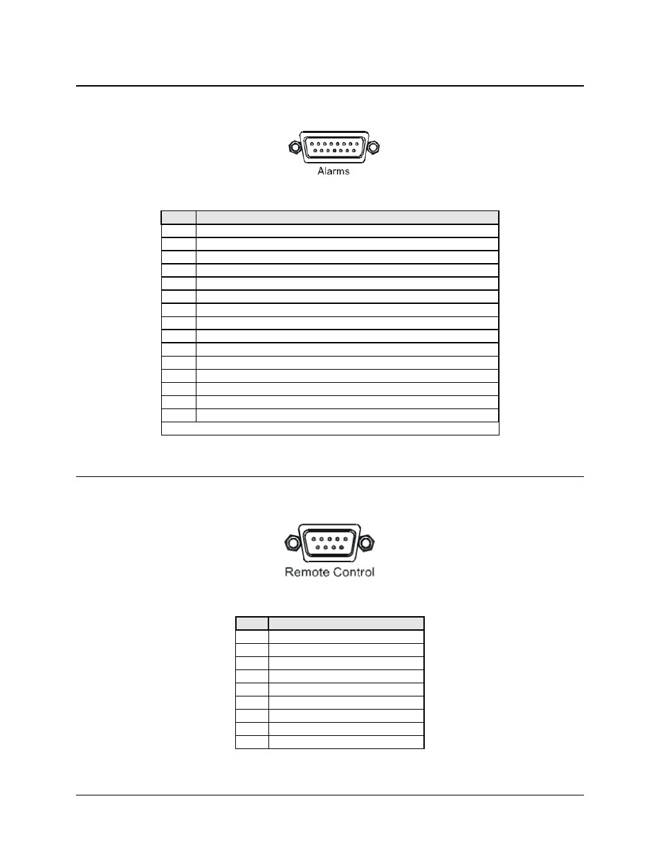
5.3 Alarms Connector, DB-15M
Table 5-2. Alarms Connector, 15-pin Type ‘D’ Male
Pin
Description
1 Ground
2
Receive AGC voltage
3
Receive Q sample (for constellation display)
4
Unit Fault Relay - Common
5
Unit Fault Relay - Normally Open
6
Transmit Traffic Relay - Normally Closed
7
Receive Traffic Relay - Common
8
Receive Traffic Relay - Normally Open
9
External Carrier Off input
10 Not
Used
11
Receive I sample (for constellation display)
12
Unit Fault Relay - Normally Closed
13
Transmit Traffic Relay - Common
14
Transmit Traffic Relay - Normally Open
15
Receive Traffic Relay - Normally Closed
Note: ‘Normally Open’ refers to the NON-FAIL state
5.4 Remote Control Connector, DB-9M
Table 5-3. Remote Control Connector, 9-pin Type ‘D’ Male
Pin
Description
1 Ground
2
RS-232 Transmit Data (Out)
3
RS-232 Receive Data (In)
4 Reserved
5 Ground
6
RS-485 Receive Data B (In)
7
RS-485 Receive Data A (In)
8
RS-485 Transmit Data B (Out)
9
RS-485 Transmit Data A (Out)
5–3