4pre-installation considerations, 1 introduction – Flowserve 400MD Logix User Manual
Page 16
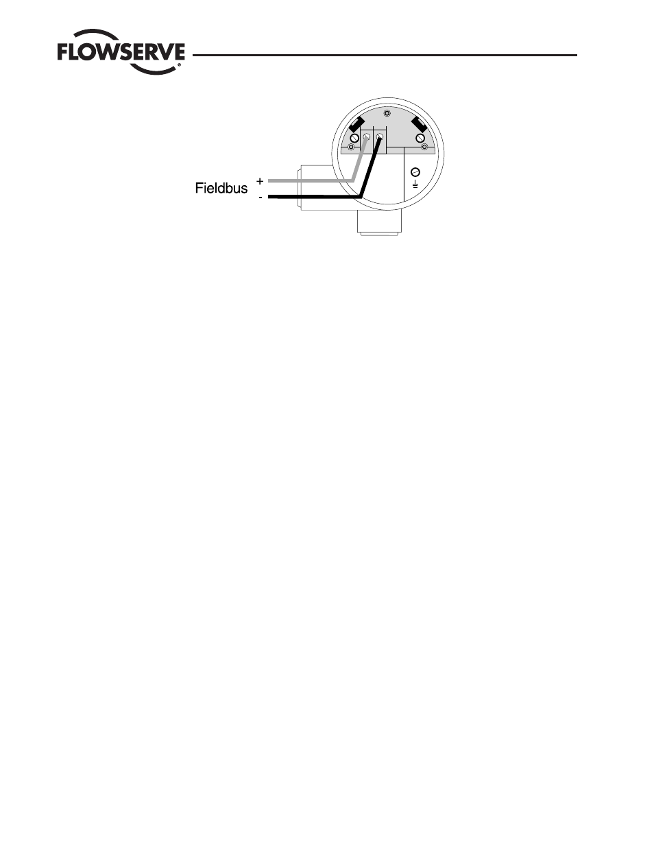
Figure 3.1 Connecting wiring device.
4. At the junction block, connect a fieldbus terminator in parallel with the device.
5. Connect a power supply , power conditioner (if needed) and a fieldbus terminator to the fieldbus cable.
!
Note: Do not connect the shield at the device connect only at the marshalling cabinet.
6. Turn on PC.
7. Turn on power supply.
8. Start fieldbus configuration application on PC. 9. Establish communications.
Once communications have established between the Logix 3400MD digital positioner and the PC, the user can then query the Logix 3400MD
digital positioner.
Assign Bus Address and Device Tag
Check the device ID of the Logix 3400MD digital positioner and assign a network node address to the device and assign tag names to the
device.
Note that the Logix 3400MD digital positioner is shipped with default node addresses and tag names that appear at start-up. These can be
changed to actual network addresses and tag names.
Typically the device tag and block tags are modified to be unique throughout the network.
Device Configuration
The user can view the various block parameters that make up the Logix 3400MD digital positioner configuration. Enter parameter values for your process
application and write them to the device. Refer to the Logix 3400MD Digital Positioner Start-up Guide for supplemental help.
Note: it is recommended to set the device address to at least 20hex or above if using the LAS feature to avoid possible conflicts with the host system.
4
Pre-installation Considerations
4.1 Introduction
This section reviews several topics which should be considered before installing the Logix 3400MD digital positioner. If replacing an existing
Logix 3400MD digital positioner, this section can be skipped.
Logix 3400MD Digital Positioner LGENIM3405-02 11/13
16