12 output splitter function block, Os block description – Flowserve 400MD Logix User Manual
Page 49
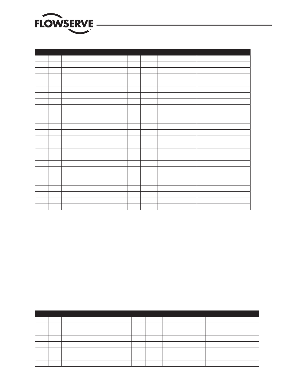
Table 8.12 IS Function Block Parameter List
Index Origin
Name
Store
Date Type
Default Value
0
STND INPUT_SELECTOR
SRW
Record
BLOCK
0
1
STND ST_REV
SR
Simple
UNSIGNED16
0
2
STND TAG_DESC
SRW
Simple
OCTET_STRING
“ “
3
STND STRATEGY
SRW
Simple
UNSIGNED16
0
4
STND ALERT_KEY
SRW
Simple
UNSIGNED8
0
5
STND MODE_BLK
SRW
Record
MODE
0x01;0x01;0x19;0x10
6
STND BLOCK_ERR
R
Simple
BIT_STRING
0
7
STND OUT
NRWO Record
FLOAT_S
0x1C;0.0
8
STND OUT_RANGE
SRW
Record
SCALE
100.0;0.0;0;0
9
STND GRANT_DENY
RW
Record
ACCESS_PERM
0;0
10 STND STATUS_OPTS|STATUS_OPTS_IS
SRW
Simple
BIT_STRING
0
11 STND IN_1
RWI
Record
FLOAT_S
0x08;0.0
12 STND IN_2
RWI
Record
FLOAT_S
0x08;0.0
13 STND IN_3
RWI
Record
FLOAT_S
0x08;0.0
14 STND IN_4
RWI
Record
FLOAT_S
0x08;0.0
15 STND DISABLE_1
RWI
Record
DISC_S
0x08;0
16 STND DISABLE_2
RWI
Record
DISC_S
0x08;0
17 STND DISABLE_3
RWI
Record
DISC_S
0x08;0
18 STND DISABLE_4
RWI
Record
DISC_S
0x08;0
19 STND SELECT_TYPE
SRW
Simple
UNSIGNED8
0
20 STND MIN_GOOD
SRW
Simple
UNSIGNED8
0
21 STND SELECTED
RO
Record
DISC_S
0x1C;0
22 STND OP_SELECT
RWI
Record
DISC_S
0x08;0
23 STND UPDATE_EVT
RW
Record
ALARM_EVENT
0;0;0,0;0;0;9;0
24 STND BLOCK_ALM
RW
Record
ALARM_DISC
0;0;0,0;0;0;0;8;0;0
The functionality of these parameters follows the standard Fieldbus definitions as defined in the Foundation Fieldbus specifications.
8.12 Output Splitter Function Block
OS Block Description
The output splitter block provides the capability to drive two control outputs from a single input. Each output is a linear function of some
portion of the input. Back calculation support is provided using the same linear function in reverse. Cascade initialization is supported by a
decision table for combinations of input and output conditions.
This block would normally be used in split ranging or sequencing of multiple valve applications. A typical split range application has both valves
closed when the splitter input is 50%. One valve opens fully as the input drops to 0%. The other valve opens as the input rises above 50%. A
typical sequencing application has both valves closed at 0% input. One valve opens fully as the input rises to 50%, and the other stays shut.
The second valve opens as the input rises above 50%, and the first valve may remain open or shut off quickly. Because this block is in the
control path, it is able to pass limit and cascade initialization information back to the upstream block.
Table 8.13 OS Function Block Parameter List
Index Origin
Name
Store
Date Type
Default Value
0
STND OUTPUT_SPLITTER
SRW
Record
BLOCK
0
1
STND ST_REV
SR
Simple
UNSIGNED16
0
2
STND TAG_DESC
SRW
Simple
OCTET_STRING
“ “
3
STND STRATEGY
SRW
Simple
UNSIGNED16
0
4
STND ALERT_KEY
SRW
Simple
UNSIGNED8
0
5
STND MODE_BLK
SRW
Record
MODE
0x01;0x01;0x31;0x10
6
STND BLOCK_ERR
R
Simple
BIT_STRING
0
7
STND SP
RW
Record
FLOAT_S
0;0.0
Logix 3400MD Digital Positioner LGENIM3405-02 11/13
49