Block descriptions, Block parameter column descriptions – Flowserve 400MD Logix User Manual
Page 31
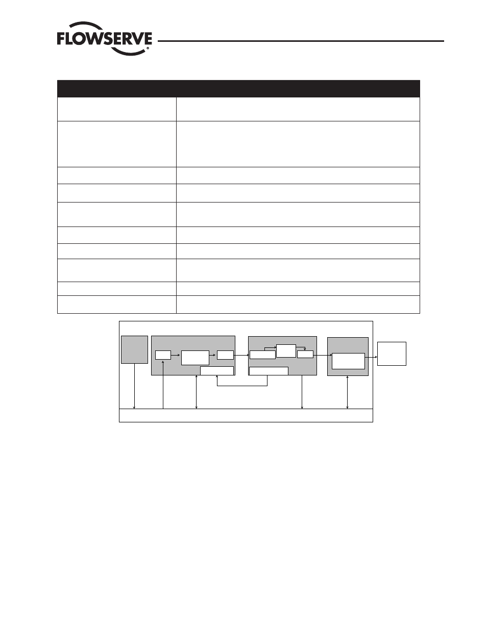
Table 8.1 Function Block Application Process Elements
Block Type
Function
Resource
Contains data which describes the hardware (physical) characteristics of the device. The
resource block does not perform any action, but contains parameters that support application
downloads.
Main Transducer
Transducer blocks Isolate the function blocks from I/O devices such as sensors, actuators,
and switches. The transducer block interfaces with the hardware to produce an output. It also
contains device-specific parameters, such as calibration and diagnostics parameters.
The main transducer block contains all of the parameters/data required for basic functionality
of the device
Tech Transducer
The tech transducer block contains parameters/data that can be used to troubleshoot or
analyze the device.
MD Transducer
The MD transducer block contains parameters/data that are associated with the advanced or
pro diagnostics of the device.
Analog Output (AO) function block
Performs basic automation functions that are integral to automated control and processing
operations. The AO block performs functions like engineering units scaling, output scaling,
alarming, and back calculation, when connected as a cascade to a PID or other block
Digital Output (DO) function block
The DO block converts the value in SP_D to something useful for the hardware found at the
CHANNEL selection.
Digital Input (DI) function block
The DI block takes the manufacturer’s discrete input data, selected by channel number, and
makes it available to other function blocks at its output.
Input Selector (IS) function block
This block is intended to be used in a forward path only and is not intended to receive signals
from the output of a controller. There is no back calculation support or propagation of control
status values.
Output Splitter (OS) function block
PID Controller function block
Performs standard or robust proportional integral derivative algorithm used in closed-loop
processing.
Figure 8.1 FBAP Block Diagram Example
Block Descriptions
Each block contains parameters that are standard Fieldbus Foundation-defined parameters. In other words, the parameters are pre-defined
as part of the FF protocol for all fieldbus devices. Additionally, parameters exist which are defined by Flowserve and are specific to the Valtek
Logix 3400MD digital positioner.
The following block descriptions list the predefined FF parameters included as part of the block as well as the Flowserve-defined parameters. A
complete description for the FF parameters is provided in the Fieldbus Foundation document FF-891, Foundation Specification Function Block
Application Process Part 2. The Flowserve parameter descriptions are included here as part of the block descriptions.
Block Parameter Column Descriptions
Tables on the following pages list all of the block parameters contained in each of the block objects. Table 8.2 explains the column headings
for the parameter listings.
Resource
Block
PID Block
IN
OUT
BKCAL_IN
Resource
Communication Stack
Algorithm
AO Block
Scaling
CAS_IN
BKCAL_OUT
OUT
Transducer
Block
channel
Value
read/write
read/write
read/write
read/write
Subscribe
Logix
Positioner
Circuitry
Logix 3400MD Digital Positioner LGENIM3405-02 11/13
31